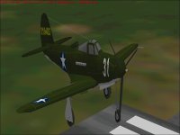
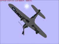
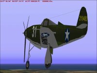
Conspicuous by Their Absence

Hello Ivan,
I had already noticed the wrong shape on the Pe-2 model cockpit - hence my diplomatic comment on the need for "properly shaped transparent cockpits". A texture correction not enough - it can only correct the lower part a bit.

The version of the IL-2 I was thinking of, is the one you correctly mention: The IL2/3M.
The original design was for a pilot and a rear gunner anyway, but was altered to single-seater for early production. This, however, proved useless as it made the plane too vulnerable, so they quickly put the gunner back in.

I got some 3-view drawings of both aircraft, and I´m just putting the scale on them as well as checking that their shape coincides with the shapes on photos.

I haven´t been able to inspect the Airacobra closely enough, as I haven´t got the source files, but I´m sure you are right about the shortcomings that you mention.

Cheers,
Aleatorylamp
 
Hello Aleatorylamp,

Sorry, I did not understand the diplomacy.

You actually don't need the source files to inspect the Airacobra model.
DPED does a pretty good job in giving the dimensions of the model though the numbers are Metric.
In fact, that is how I am doing it myself.

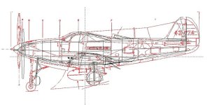
Here is an overlay of the Aircobra's Wire Frame onto a scaled version of Paul Matt's drawing from Historical Aviation Album from 1965.
I believe these are pretty good drawings. They appear to have the correct shape and have a few critical dimensions labeled.

After looking at the comparison, I am actually VERY impressed with Eric Johnson's work.
The proportions are much better than I had thought and errors appear to be due to a single misinterpretation of dimensions.
You might look at the overlay (Reference Drawing in Red) and wonder why I came to that conclusion because there are a lot of differences.
Production versions of the Airacobra had a length specification of 30 feet 2 inches for ALL versions.
What isn't obvious is that this dimension is from the tip of the SPINNER to the end of the Rudder.
The length of the cannon barrel out the front is not included.
The cannon barrel shifted with recoil and differed in length based on whether it was a 20 mm or 37 mm.
I believe Mr. Johnson used a P-400 profile as a reference and used the length specification as the OAL with the cannon included.
In addition he was limited to the 0.1 foot resolution while we use a 0.01 foot resolution with AF99.

- Ivan.
 

Attachments

  • P-39_Overlay_Compare.jpg
    P-39_Overlay_Compare.jpg
    61.1 KB · Views: 0
Hello Ivan,
Of course... As well as Dped, Aircraft Animator would also be easy and fast to
inspect models.
I hadn´t got round to it because I´ve been quite busy with
the 2 Russian ones.

Looking into it, I noticed what you said about the diamond cross-section.
The way of making the tailplane component out of triangles radiating out from
the root was quite a usual approach in those days. Personally, I prefer to make
the leading edge thicker, so I tend to build them more like a wing, although the
resulting airfoil is a bit flatter.

Perhaps the dimensional error you saw earlier errors came from the AF99 blueprint,
which we
discovered some time ago deforms the overall dimensions making the
model
too long and not high enough.

I´m glad that Eric Johnson´s Airacobra model is better than you thought!
In case the AFX you have is good enough, it may be simpler to make the
necessary improvements with that istead of doing a complete scratch build:
New transparent canopy, canopy frame, rounder wheels, longer nose-gear,
corrected flaps - perhaps it
won´t be so bad!

I´m still setting up the drawing board to start on the Russian ones.
Cheers,
Aleatorylamp
 
Last edited:
Hello Aleatorylamp,

I really wasn't even involved in flight simulators at all "in those days" when this model was built so I don't know what the practices were.
I probably began with simulators a few months after Combat Flight Simulator first came out and then put it away for months when I could not get it to work at all on my computer (which happens to be the same basic machine as I use for Development today).

The dimensional errors are not from the AF99 Blueprint because I am using DPED to get my screenshots of the wireframe.
The Plain Flaps are not actually in EJ's AFX; It has Split Flaps like it should.
It actually doesn't matter how good the AFX actually is. I have learned my lesson.
To bring it to where I want it to be would take about as much work as it would to build from scratch.
I have already rebuilt two AFXs.
The Me 109E Trop was a good AFX to start but needed too many edits.
The P-38J I used for AIR file development was another of EJ's AFXs but I only got to about 95% of where I would take it for a releasable project because I was only using it for one specific purpose..... And for some quick and easy work when I got frustrated with my normal projects.

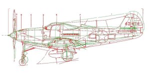
Just for amusement, I decided last night to see what would happen if I re-scaled all the Parts in the AFX to a slightly larger size.
I used a multiplication factor of 1.0191 and wrote a script to run through all the Parts from a directory listing.
(This only took about 5 minutes to do. Adjusting the Structures took perhaps another 5 minutes.)
What this process did not catch was Structures and of course Texture Mappings but the result was interesting as shown in the screenshot
The new wire frame is in Green.
I seem to have miscalculated the scale increase a little.

I am trying to decide if I should write another program to edit the old texture mapping to match the new Parts.

- Ivan.
 

Attachments

  • P-39_Overlay_Compare2.jpg
    P-39_Overlay_Compare2.jpg
    59.6 KB · Views: 0
Hello Ivan,
I wasn't around fs until 2004, so I got the info just looking into the afx's that were about 6 or 7 years old at that time. The FS98 model I have doesn´t have the split flaps, but of course, it´s not from the AFX you have.

Your amplification of the Airacobra model size sounds quite fascinating and judging by the previous drawings compared, would seem very close! Hope you get it where you want.

Updated paragraph:
I hadn´t see the attached screenshot until now because I´d answered this post on the mobile phone, which doesn´t show attached pictures. All the model really needs now is a slight general giration to bring the tail down a bit, and a longer nose-gear, perhaps...

I suppose the criteria to use for a re-build of an existing AFX can be misleading. It often happens that the more you progress, the more crops up that could use re-working, and at the end, it would have been simpler to start from scratch!

I've just done the Shturmovik's spinner, just to get me going... This plane, as well as the Pe-2 twin, have slightly different lines form the more usual designs, so it´s going to be fun! The Shturmovik is a bit reminiscent of the Stuka, with general Me109 influences perhaps...

Cheers,
Aleatorylamp
 
Last edited:
Hello Aleatorylamp,
My involvement with flight simulators was earlier by around two years, but I didn't try to find others' AFX projects until much later.

I actually have no real plans for this AFX other than to use it to experiment with situations that never occur in my own projects.
I don't really know if the utility I used to resize the 3D model is completely stable or not.
I had found when examining the model further that the Wing Span was also short so it made sense to expand everything in all directions.
The dimensions are better but they are still not quite correct.

As mentioned before, I don't believe it makes sense to use someone else's AFX except to examine.
I like a project to be my own work, so this model really serves just to represent my competition if I should ever build an Airacobra.
Besides, there isn't a single Part that would be retained in its present form into the final project anyway.
The Fuselage only has eight sided cross sections and my own projects have a twelve sided Fuselage.
It still would be interesting to see how much I can improve the model with a few reworked pieces.
It is nice to work on a project that has absolutely no requirements once in a while.

- Ivan.
 
Last night I decided to see what I could quickly edit in EJ's model.

There is a strange thing that seems to happen when a Part with concave edges is displayed in CFS. The concavity is lost in the normal display but shows up again when leaving the simulator or bring up a menu. (Press Esc or Alt Keys.) Sometimes this happens and sometimes it does not. It appears to happen more often when the Part has many vertices or is not in perfect alignment along the primary axis of the model.

This was a problem in the original model and can be seen in the Main Gear Doors and in the Pitot Tube.
I decided to make a correction to the Pitot Tube because it was easier and the Pitot was untextured.
An interesting observation when making this edit is that the entire model does not use any Glue Parts and it is relatively bleed free.
It now has its first Glue Part. The lack of Glue Parts might partly explain why the Parts Count is so low. I can easily see adding another 50 Glue Parts to rely less on AF99's automatic (and unpredictable) Glue sequences.

The other thing I changed was to replace the Propeller with MY standard setup.
Just a simple Propeller change seems to have radically altered my perception of the appearance.
Note that the method I am using for corrections (actually additions) were not available to Mr. Johnson when he first built the model so the fact that I can improve things using later tools is no commentary on his work.
Contrast this Propeller with 0.01 feet precision with the original Propeller which was limited to 0.10 feet precision.
I know I could never have gotten anything done with the earlier tools.

I actually like the shape of this Propeller enough that I may just save it for other projects.

- Ivan.
 

Attachments

  • Airacobra_Propeller.jpg
    Airacobra_Propeller.jpg
    45.8 KB · Views: 0
Hello Ivan,
The old model definitely looks very nice.
It´s always a good sensation when an idea for improvement works out, more so
if the results are better than expected.

With the success over the original model I bet the author E.J. would be pleased.

It´s interesting how a model that was up to standard in those days can be much
improved with a few able strokes using the more modern tools you mention, and
also how some seemingly minor improvements have a greater overall effect on the
general impression.

Cheers,
Aleatorylamp
 
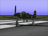
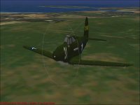
Last night I tried some automatic remapping of textures.
This is the result.

I had to do multiple attempts so I worked from the original AFX.
Scaling is
Left-Right: 2.25x
Fore-Aft: 1.25x
Up-Down: 3.33x

The rather extreme stretching / scaling is because it isn't easy to tell whether a texture is remapped correctly if there is only a 2% difference.

While the remapping worked out pretty well, the original Stretch did not seem to work for all the pieces this time and I need to figure out what happened. This is probably a result the instability that I mentioned earlier.

- Ivan.

attachment.php
attachment.php
attachment.php
attachment.php
 

Attachments

  • Remap1.jpg
    Remap1.jpg
    49.1 KB · Views: 0
  • Remap2.jpg
    Remap2.jpg
    47 KB · Views: 0
  • Remap3.jpg
    Remap3.jpg
    30.2 KB · Views: 0
  • Remap4.jpg
    Remap4.jpg
    38.8 KB · Views: 0
Hello Ivan,
So your programme has to read each texture-spread, and re-scales
it by the same value you are applying to the model.
Interesting, and time saving when applying corrections!
Is each axis done independantly or are the three done at the same time?
Cheers,
Aleatorylamp
 
Hello Aleatorylamp,

My program is just a minor modification from the one I used earlier to Move Texture mappings after moving the CoG of the pieces of a model. In fact, there are very few differences and the total changes are fewer than 20 lines of code.
The Input File and Multipliers are specified on the command line and that is about it.
It works fine for my models but is having problems with some pieces on this model because some of the pieces are shifted in the final assembly process here. Since I always build thing in place, I would never see this in one of my own models which is why it is more useful to test with someone else's models.

I need to do a bit more programming to handle that situation and things may get a little more complicated.

- Ivan.
 
Hello Ivan,
Interesting. Yet another annoying aspect of finding elements simply
pushed into position after having been built somewhere else!
That´s why I stopped re-working other people´s AFX a long time ago!
But that´s only my humble opinion, as obviously it´s not annoying for
those who do it.

I was wondering if your little programme would be able to shift
vertices
so that a model would be 1 inch higher and 1 inch lower from
the
centreline. At the moment it´s only a portion of the fuselage, and
untextured.

The problem is that the 3-view I was using at first seems to differ by

this amount from a second set I´d found, which seems more reliable.

Update:
I decided to correct it part by part, and it´s fine now.
I should have used the second 3-view in the first place, but it was a .png file and
took some work before I could make it editable to put a scale on.

Cheers,

Aleatorylamp
 
Last edited:
Hello Aleatorylamp,

Glad you have things managed.
I presume you are discussing the Sturmovik.
What you encountered is why I spend a LOT of time looking for drawings and editing them before ever cutting any virtual metal.
At the moment, I am seriously considering building the Airacobra, but haven't found a set of drawings I completely trust yet.
The Paul Matt drawings look good but there are some details I am not so sure of.
There are a bunch of drawings from some Polish language books but they don't show all the views I want (Profile with Gear Down).

The program I wrote is called "StretchIt".
It takes a Part and multiplies its coordinates by a set of three constants specified on the command line.
All I did was to execute this program with a multiplication factor of 1.0191 on ALL the Parts in the P-39D project folder.
The problem was that many things cannot be seen with only about a 2% increase, errors just don't show up, so I did a much greater stretch as a test to see what else would show up.

The problem is that the pieces that were moved around in the Assembly process also need their adjustments multiplied and my programs don't do that at the moment.
This screenshot shows what happens when the pieces that were moved in the assembly are also displayed.
As you can see, things get quite interesting.

There are few enough pieces moved around that I could easily make the adjustments in the AFA file manually if correcting the model were my primary interest but it isn't. I am just using it to experiment on because my Development Machine doesn't choke on it as much as with more complex models.
By the way, I also found that there were some Glue Parts used already. There just are not very many.

- Ivan.
 

Attachments

  • NotWellAdjusted.jpg
    NotWellAdjusted.jpg
    41.5 KB · Views: 0
Hello Ivan,
Looking at your experiments, an accordeon comes to mind, but with bits
and pieces flying out of it while you squeeze it into different positions!
Ha ha!

As regards problematic source drawings, it often happens that it is only after
I actually start building, that I notice flaws and incoherences which were not
apparent during the initial preparations.

It then requires additional preparations to source material, and the resulting
model modifications before I can continue. In this case it´s only the Nose
elements that needed adjusting, so it was no problem!

Anyway, that Stretchit program does sound like a useful little gem!

I see that you are quite getting into the Airacobra. Good luck if you decide
making a new one!

The idea of the engine being on the CoG seems to be quite an appealing one.
I remember when racing cars came out with the novely of the middle-engine
approach.

Cheers,
Aleatorylamp
 
Hello Aleatorylamp,

The StretchIt program has yet one more great use.....
The Multiplier does not have to be positive!
When working on my SBD-3 Dauntless Dive Bomber, I needed a Gunner in the aft Cockpit.
The easy way to get this was simply to take my standard Pilot model B and use StretchIt to make a version that faced backwards.
I forget if I did the same thing with the Ju 87B Stuka.

I paused the updates to the Thunderbolt because it is really dependent on additional research and AIR file tuning at the moment.
The research is not that bad but boring and I do not have a machine that is reliable enough to do significant flight testing.

The Game Machine finally stopped booting about a week ago. The hard drive does not appear to power up.
I MAY have the pieces necessary to repair it, but my Daughter wanted to be involved in the hardware aspect of the repair and she is busy for the next few days.
There is yet another possibility of setting up a second Development / Game Machine with a spare mini Tower computer I have as a spare.
I found a graphics card but I don't know if it works or not.

Regarding good drawings and research:
I always try to find as much as possible beforehand. The case of the Airacobra is special because it had some very strange flight characteristics which I want to allow for in the AIR file which means I need to be more accurate than usual in the representation.
There is also a LOT of data to be organised and as usual, some of it is conflicting.
Even with the research beforehand, there is always bound to be a problem in drawings but with better research, the problems are not likely to be as serious.

- Ivan.
 
.afa and .afx files

Hello Ivan,
The main cause for my initial problems with a model is my impatience.
After a week or two few of looking for information, inspecting 3-views
and scaling them, and repeatedly looking at the same stuff all the time,
I get pretty bored and my fingers start itching to get building...

So the little StretchIt program also allows rotating a complete object.

Interesting! Scaling, rotating and also moving things... I remember you
re-positioned the whole Curtiss-Wright AT-9 Jeep Build to get a better
CoG position because of a cabin bulkhead bleed.

A cool tool lacking in AF99, where everything has to be done by hand,
piece by piece.

I suppose your programme would process the .afx file.

Looking into the subject of objects simply shifted into place being built
elsewhere, I looked into the .afa file and found something interesting,
that you also must already have seen:

The first three entries after the title or name of a part correspond to
the shifted, pushed positions: left/right, fore/aft and up/down, in that
order. If an object hasn´t been shifted, these three entries remain at Zero.

Unfortunately the .afa file won´t show the positions of an object´s vertices,
but then I looked into the .afx file, and lo and behold, it was very obvious
where all
the vetrices for each part were placed!

Perhaps I could write a QBASIC program to process .afx files without ruining them,
as QBASIC has a very complete set of instructions related to manipulating text.
It could discover and alter vertex x-y-z
coordinates to re-scale something, for example.

Once again, I wish you the best of luck with your new (and old) development
machine. It´s nice that your daughter is also interested in computer hardware!
By the way, I sometimes use a nifty little Hard disk Scanning Programm called
HddScan to test hard disks, freeware available at http://hddscan.com.
One of the faster tests it does is a read-only scan of the surface, and informs you of the
sector reading speed, so you can see the quality of the surface, not only totally defective
errors.

Cheers,
Aleatorylamp
 
Last edited:
further to editing an AFX

Hello Ivan,
Writing a QBasic programme to open the AFX as a text file, locate
the vertices to scale them up or down by a certain value, is possible
but will be quite difficult.

The theory looks quite straight forward:
Looking into the AFX file with a text editor, it seems that every
aircraft part with its name label exists as in the AFA file, but has an
added section after it, repeating the name label, which contains
the vertex information, amongst other things.

Most relevant lines for the vertices appear to start with two inverted
commas and a comma, except for Structures, that have the name of
the cross-section type written in, between the inverted commas.
(Now I understand why you have to process structures separately!)

I know how to make QBasic write data to a file and save it to the disk,
and then retrieve it later to read it, but now I have to see how to open
any text file to read, and then how to make the programme identify the
relevant vertex data lines... no small feat. I wonder if I´ll get very far...

Anyway, it is intriguing, to say the least.
Cheers,
Aleatorylamp
 
Hello Aleatorylamp,

I was once just as impulsive with getting into building a 3D model, but the cost of having to redo things was too high.
The output was greater, but the learning and quality of models was not as good. The chance of making a mistake is much higher when one doesn't take the time to think things through.
That is why I have other little projects of no consequence to work on when the urge to SEE results hits me.
This FS5 P-39D is one of those projects.
Also, I often find things that are not quite right a few weeks after a project release and sometimes they are not worthy of a new release, but I take the time to correct them and that adds up to a lot of little tasks.
At the moment, I am avoiding a couple tasks that should be done for the Macchi C.202 and C.205 because they look tedious.

The StretchIt program actually is fairly low capability. It only works on ONE AF99 Part.
When it is used on ALL the parts, life gets interesting.
The StretchIt program also doesn't do rotations; It only stretches or shrinks each axis by a multiplier.
I don't think I had originally intended it for any great purpose. It just happened to be a natural follow-on to the MoveIt program.

I had already figured out where the offset numbers were located in the AFA file. Those are the ones I am trying to edit now.
I actually never intended to edit the AFX file because often there isn't an AFX at all.
I use AFX files for archive purposes when there is a stable version that is worth archiving.

If you can write QBASIC programs to do the same thing with the AFX, why not do it? I obviously thought it was a worthwhile task.
I actually found I was a bit rusty with some of the C Programming but it came back pretty quickly. In playing with this new program, I also found a very slight rounding bug that exists in the old StretchIt program as well, so there are a couple things to fix.
I am guessing that you won't be nearly as rusty because you are staying pretty active with the development stuff.
The nice thing is that the source code is pretty standard C/C++ so it is compatible with the MSVC compiler on my Laptop and the old GNU C compiler on the Development Machine. The EXE files from the Laptop will run on the Development Computer, but the reverse is not true. There isn't room on the Development Computer to install MSVC.

Regarding the mid-Fuselage Engine location of the Aircobra, in my opinion, it really was not a good idea. There are too many other things that needed to go there. I have actually been collecting information on the Airacobra for a very long time even before I had thought it was a worthwhile CFS project. This one needs to be more precise than usual to make sure that I don't gloss over the goofy flying characteristics of the real aeroplane.

- Ivan.
 
Hello Ivan,
Well, with age I seem to be getting more patient slowly. It used to be
much worse and I wouldn´t notice flaws on the source material until
a model was well underway. This time it´s just the nose section and
not a widespread overall glitch mess-up.

Re. the QBasic Text-Editor come Vertex Changer I´m planning, now
I´m looking for how QBasic opens existing Text Files, as I keep getting
a Non-Existent File Error. This never happens with the data files I can
make a Qbasic Program create, save and later use. I suppose it must
be a path error. I still have to learn elementary things I never needed
before, but it shouldn´t be too difficult.

Anyway, to your StretchIt program:
OK! When you made the head face backwards inverting the longitudinal
axis, you pulled the face backwards through the head and out at the
back, the end effect looks like a 180 degree rotation, but of course it
isn´t one. Right and left don´t change around either! Sorry!

As regards your MoveIt Program:
This I believe does the whole model with all parts moving together,
structures being done later in a second stage. With the Curtiss Wright
AT-9 Jeep obviously you worked this on the AFX.

The question is, if you can´t access the AFX because there isn´t one,
and obviously neither will there be an AFA, then the only other file you
can use would be the SCASM Code.

Would you for example apply StretchIt to an identified portion of the
SCASM Code, like the pilot´s head, a) pull it back to front to make
it face backwards and b) change it to the gunner´s position?

I´m just curious, and I hope I´m not being a pest
asking these questions!
Cheers,
Aleatorylamp
 
Much Too Complicated

Hello Aleatorylamp,

I believe you are assuming that I did much more than I actually did.
On my own projects as with other projects, there NEEDS to be an AFA file to have something to produce.
In fact there may be several AFA files. I usually use another AFA for the Canopy Frame so that I can generate a Component to flip inside out using SCASM for the Interior Canopy Frame.
I sometimes use even more AFA files to build just one section of the Aeroplane that I am interested in at the moment.
I don't generate the AFX file until I am ready to archive the project, thus there is may not be a AFX especially for a project In development.

The reason I was getting so specific about the Rotation versus Stretch is because I was also working on a program to Rotate a Part about an axis. It was started years ago but never completed because I found that I didn't really need it that badly.

The MoveIt program only works on a single Part. I just use it on ALL the Parts in a directory if I intend to move the entire aeroplane.
There is also a CMoveIt for Components, but it isn't necessary when all the Parts within the Component are moved by something else.
There is a StructMoveIt for Structures as well.

While it is possible to edit SCASM code, I do that as little as possible there because I prefer working on something I can examine visually more easily.

I finished the StretchTexture program earlier today and tested it on the original P-39D AFA file.
The Screenshots seem to show that things are working.

- Ivan.
 

Attachments

  • RemapSucess1.jpg
    RemapSucess1.jpg
    38.4 KB · Views: 0
  • RemapSuccess2.jpg
    RemapSuccess2.jpg
    34.1 KB · Views: 0
  • RemapSuccess3.jpg
    RemapSuccess3.jpg
    47.5 KB · Views: 0
Back
Top