Gauges for Combat Flight Simulator

Donation drives

SOH Bandwidth Drive 2025

Goal
$3,500.00
Earned
$1,040.00
This donation drive ends in
The bitmaps for the gauge took a couple evenings to get to the way I wanted them.
The actual reprogramming took much less than one evening working from the Corsair 500 Knot ASI.
I have tested the gauge and it works, but don't have a good A6M panel as a host. All the panel updates described earlier in this thread have been lost even though the gauges can be reproduced.
I also still have yet to find a current MDL with the latest updates since the initial release in 2013.

- Ivan.
 
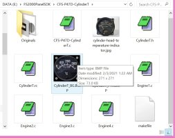
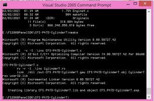
For those of you who might be interested in setting up a Gauge Development environment, here are a couple screenshots to give you an idea of how I do things using the FS2000 SDK for CFS1 Gauges.
It doesn't quite follow all of the SDK example structure because I wanted things connected to one gauge in a single director for ease of locating and editing.

The Gauge is for Cylinder Head Temperature based on the appearance of that from the P-47 Thunderbolt.
It was created as a Gauge SET so that there is a separate gauge for Engine 1 through Engine 4.
It makes the resulting library a bit bigger but saves the hassle if someone down the road wanrs to borrow the set for use on a 4-engine aircraft.
There have been a couple cases of folks around here finding a suitable appearing set of gauges and finding that they only had a set of three instead of four.

The first screenshot shows the needed source code for a gauge set.
Note that "Originals" is the directory used to store the pieces used to create the background or pointer bitmaps.
There is a JPG image of what the real gauge actually looks like which of course is not essential, but is a good reference.
When I am not so lazy, there might be a different background for each of the 4 gauges with slightly differently timed screws, etc.

The second screenshot shows an execution of the nmake build utility on the makefile that contains build instructions and dependencies.

- Ivan.

P47D-CHT-GaugeSource.jpgGauge-Compile-Sequence.jpg
 
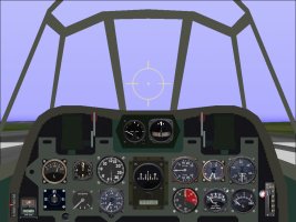
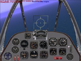
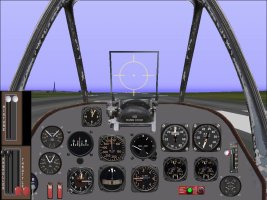
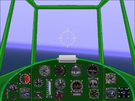
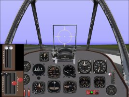
Here is what the A6M panel looks like with all the latest gauge updates.

- Ivan.


PanelUpdates.jpg
 
Last edited:
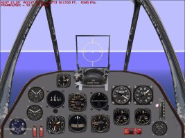
Here is a recent (last night) panel creation for a late model P-38 Lightning.
In this case, it is specifically for a early model P-38J without the dive recovery flaps.
I believe that around half of the gauges in use here are actually newly programmed twin-engine gauges.
The rest are stock P51D gauges.

- Ivan.

P-38J_MinorPanelUpdates.jpg
 
Ivan's Workshop is in the midst of working on a new gauge. It isn't necessarily anything unusual, but it is something that the technicians at Ivan's Workshop have no experience with.
A new gauge is an incredibly TEDIOUS endeavour, and I haven't even gotten to the debugging stage yet.

As for New Gauges in the plans, I figure the P-38 Panel above deserves about another two gauges at least and the A6M panel should have another two gauges maybe. None of those should be particularly complicated but all of them are on the tedious side.
It is quite amazing how many of the older projects could use an actual panel of their own instead of a stock panel.

- Ivan.
 
The new gauge is going to get moved to the side to allow for a couple other useful "instant gratification" type projects.
It gets a bit discouraging to be working constantly on a single project when the progress and completion are uncertain, so there will be a couple other hopefully quick projects going on simultaneously.

- Ivan.
 
Here is another screenshot of the current P-38 panel with the dual pointer gauges a bit more obvious.
The ignition for Engine 2 (The Right Engine) is switched off.
The things to look for in the screenshot are the following:
The dual magneto has the Right ignition switched off. (Lower Left of the panel)
The fuel gauges above the magneto switches show no difference between Left and Right.
That is because even though only one engine is running, it is drawing from both sides. Side effect of no fuel selector.
The Tachometer at Upper Right of panel shows both Engines at 3000 RPM. One is providing power, one prop is windmilling.
The Manifold Pressure gauge to the immediate left of the Tachometer shows the "L" pointer at 55 inches Hg while the "R" pointer shows only 25 inches Hg.
The two Three-Way gauges below the Tach and MP gauges show about the same Fuel and Oil Pressure for both engines but the Oil Temperature is much lower for the Right side gauge.
The round gauge at the lower right of the panel is the Radiator Temperature gauges. The Left Engine shows just under 100 degrees. The Right Engine shows near 0 degrees.

Seems like everything with the exception of the fuel quantity gauges, everything is about where it should be for a P-38 flying on one engine.

- Ivan.

Engine2_Off.jpg
 
This was an experiment that turned into a bit more than just a minor diversion.
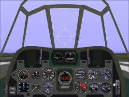
The Type 92 Compass at the center of the instrument panel is completely functional.
It isn't quite as pretty as I would have wanted. There are only so many ways that low resolution numbers can be done and none of them really look very good. There is a minimum dimension which is required to be able to do reasonable looking numbers no matter the angle. This is just a heavily modified copy of the SDK Whiskey Compass.

The runway is at a heading of 20 degrees.

- Ivan.

Japanese_Type92_Compass.jpg
 
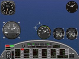
Here is a screenshot of a US Army Type B-11 Cylinder Head Temperature gauge I just finished working on.
It is of course much bigger on this screenshot that it would be mounted on an actual panel, but when testing, one has to be able to see exactly what is happening and if there are any peculiarities.
Gauge is on center left of screen.

Engine one (Left) has ignition off to watch the temperature drop.

The bitmaps for this gauge were a serious pain to draw. The programming was pretty trivial.

- Ivan.

B11_CylinderTemp.jpg
 
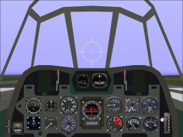
Here are some minor visual improvements on the Type 92 Compass.
Seems like these days I am finding just about every way to make a mistake and correct it later IF I find it.
On to the next project or is it time to resume the prior one?

- Ivan.

Compass_Final.jpg
 
This was the prior project. The technicians at Ivan's Gauge Factory had a really rough time with this one.
A Twin Engine Throttle is nothing really special, but it gives enough experience to carry over to the actual target.
This gauge should be suitable for the center console of a B-25 Mitchell which is where it is being tested.
The first test was to confirm that Throttle 2 (Right Engine) actually worked.
The second test was to cut both engines by reducing their mixture. It didn't take much.

This version of the AIR File of the B-25C Mitchell does not have auto mixture.
It was an old one but that was what was on the Game Machine. I believe the final version will have auto mixture because on most US WW2 service aircraft, the typical operational practice was to put the mixture setting on "Auto-Lean" for Cruise and on "Auto-Rich" for Military and Emergency power.
There was a setting for Manual Mixture and when used, it was possible to get perhaps another 5 HP out of a 1000 HP engine but this needed steady state flying and observation of gauges such as the EGT gauge to fine tune the mixture. On a fighter in which altitude and throttle are often changing, it was just run on Auto-Rich.
In CFS, we cannot do both as could be done in real life, so I choose Automatic Mixture control in the final product these days.

- Ivan.


Engine2_ThrottleTest1.jpgB2X_ThrottleGauge.jpg
 
At this point it is time to step back and see what kinds of gauges are still necessary to complete either a B-25C panel or a P-38 panel.
The problem is that often, the actual gauges that are on the panel may not add useful functionality for the Virtual pilot. Aircraft designers also have a tendency to put levers and controls in rather in convenient locations that are hard to simulate such as landing gear or flap controls next to the seat or sitting very low on the instrument panel in an area that would be off the screen.

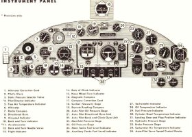
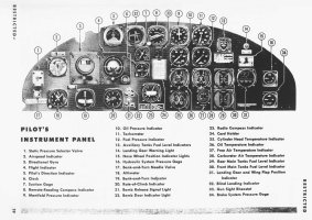
Attached is a manual page for the panel and instrument layout for an early model B-25.
From here, one can see that the function of a Directional Gyro or Compass has three different instruments on the panel.
For our purposes we really NEED one. If we have room, adding a Magnetic Compass may be a good idea, but usually real estate is tight on the panel.

- Ivan.

Panel from TM.jpgptm_sample.jpg
 
Here is the first try at a set of Throttle gauges for a P-38 Lightning.
Note to self: Next time, write down the height and width of the gauge BEFORE trying to set it up.
That way, perhaps there is a better chance of getting the aspect ratio correct in the CFG file.

I think it looks good enough, but there is a rather silly bug that should not be hard to fix.

- Ivan.

P-38_ThrottlePanel.jpg
 
There appears to be some unintended interaction between the two gauges that I can't seem to pin down at the moment.
The code looks good, but the Mixture gauge interferes with the main Throttle gauge. Looks like this will take a bit longer than I thought.
It is kind of a strange arrangement but that is actually how the Throttle, Propeller Pitch, and Mixture control levers are arranged on a late model P-38 Lightning.

- Ivan.
 
Just when I thought the Japanese Type 92 Compass was done, I came across a reference which described how it really works.
Apparently the CFS2 folks and I both got it wrong. The outer ring does not rotate except by hand to note the preferred heading.
This explains why the vast majority of the photographs do not show the outer ring coinciding with the actual compass reading.

Back to editing the Type 92.....

- Ivan.
 
Back
Top