Gauges for Combat Flight Simulator

Japanese Manifold Pressure Gauge

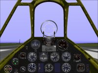
One of the things that has bothered me for a long time with the panel that I created for the A6M2 and A6M3 was that although the general appearance of the panel was "in the spirit" of the original with concessions to CFS functionality, some of the gauges were not very good matches. They are functional, but the appearance is quite different from the actual Japanese Gauges.

Recently I have been involved in forum discussions about the performance of different versions of the Mitsubishi A6M and was reminded of the panel issues when I took the CFS models up for some "Fun Flying".

The Gauge that bothered me the most was the Manifold Pressure / Boost Gauge.
The actual gauge that I was using was the stock Me 109 version which reads in ATA.
I figured a new Japanese Manifold Pressure Gauge would not be that difficult and started working on the bitmap for the background last night.

I thought the background would be fairly easy, but it actually took a few hours to get it looking the way I wanted. The only things that I could use from other gauges was the frame and screws and the colour scheme.
Lining up tick marks is just plain tedious!

The first image is of the actual gauge as removed from the first A6M2 restored and test by Allied forces in 1942.
The second image shows the aeroplane in which this gauge will be used.
The third image shows the panel with the new gauge installed.

Oops, Unable to upload images. Will add images when I can figure things out.

- Ivan.
 
A6M Instrument Panel

Attached (finally) are images of the new Boost Gauge that was created for the Mitsubishi A6M series.
Hopefully the attachments will work this time.

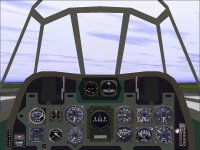
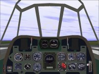
As can be seen, the old panel has gauges in about the right place but needs a few changes to be a bit closer.
The Manifold Pressure / Boost Gauge was the first change.
A German ATA Manifold Pressure Gauge just didn't seem right.

Note that this particular gauge is quite different from the Japanese Army Manifold Pressure Gauge shown here:
http://www.sim-outhouse.com/sohforu...ht-Simulator?p=1089767&viewfull=1#post1089767

As some folks may already know, the Japanese Army and Navy did not really cooperate in anything until very late in the war and didn't use the same equipment when they could avoid it.

When I first began working on this gauge, it was for the A6M2 or Type 0 Mk.I Fighter.
I had thought that with the increased boost pressures in the engines for the Mk.II (A6M3 and A6M5), I would need a new gauge.
I was rather unpleasantly surprised to find out that the later fighter used exactly the same gauge even though it was incapable of displaying the maximum boost that the new engines could achieve.

From a functional standpoint, the gauge that needs an update the most is the Air Speed Indicator.
The Japanese Navy used an ASI that displayed in Knots. This is the same kind of gauge that I needed for the F4F Wildcat and other USN fighters.
The issue to be decided now is whether to build the gauge as one that shows the full range of values in two revolutions or just one.
On a real aeroplane, there are plenty of visual cues to make it obvious whether the airspeed is 80 Knots or 280 Knots, but there is much less inside a simulator.

- Ivan.
 

Attachments

  • A6M_OldPanel.jpg
    A6M_OldPanel.jpg
    82.7 KB · Views: 0
  • A6M_NewPanel.jpg
    A6M_NewPanel.jpg
    82.4 KB · Views: 0
A Better Fuel Selector

In the previous screenshots, it can be seen on the lower left of the panel that the Fuel Selector being used is from the stock Hawker Hurricane Mk.I.
I picked it because it had the correct selections of Right, Center, and Left Fuel Tanks and did not have the distinctly American look.

This gauge actually has a rather blurry looking set of bitmaps and typical single mouse area of stock CFS fuel selectors; My preference if a knob can be turned in two directions is to have two mouse areas so the pilot actually has a choice other than to cycle through unnecessary positions to get to a destination.

Another problem with this gauge is that there appear to be four tank selections but only three are selectable. PORT, CENTER, and STBD are selectable. RESERVE (lowest position) is not selectable.
This is quite interesting because there only happen to be three actual fuel tanks in a typical Hurricane.
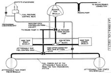
In the diagrams in the Pilot's Manual, they are refered to as the Port and Stbd Main Tanks and the Reserve Tank. (See Diagram)

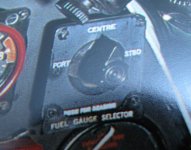
The actual gauge on the panel of the Hurricane actually does not have the label "RESERVE" at all which is not surprising because the Center Tank is the "Reserve" Tank. Instead, the label should actually read "PUSH FOR READING" (See Photograph)

As usual, for a replacement gauge, generating new bitmaps will be the difficult part. The actual programming behind the gauge is almost identical to prior fuel selectors and is pretty trivial.

- Ivan.
 

Attachments

  • Hurricane_FuelSystem.jpg
    Hurricane_FuelSystem.jpg
    33.1 KB · Views: 0
  • HurricaneFuelSelector.jpg
    HurricaneFuelSelector.jpg
    99 KB · Views: 0
Markings

Attached is an image pulled from the actual Hurricane Multi Gauge.
Observant folks may have already noticed that there were other differences in markings than the ones I pointed out.

As can be seen, M$ apparently didn't like the British spelling and changed CENTRE to CENTER
We have already mentioned that "RESERVE" should be "PUSH FOR READING"
The attached label plate doesn't actually say "FUEL TANK SELECTOR", It says "FUEL GAUGE SELECTOR"

Since my gauge is really a "generic" fuel selector rather than specifically for the Hawker Hurricane, I will probably use the same kinds of markings as M$ did.
One has to wonder though: In many circumstances, there may be a choice between authenticity and practical use on a flight simulator Computer Screen. Certain things do not make sense on the flight simulator because the interface is so different.
These differences and choices to address them can lead to a pretty long discussion.

On small gauge BMPs like these, M$ seems to prefer having overlays for the entire gauge face for each pointer position rather than just a pointer overlay. My own preference is for a separate set of overlays for pointers instead of the entire gauge face.

Next step is to make sure I have the proper screw heads to use for this gauge.

- Ivan.
 

Attachments

  • Hurricane_FuelSelect_1.BMP
    11 KB · Views: 3
Updates to P-40N Panel

Hello All,

The Fuel Selector for the Hawker Hurricane didn't get forgotten. It just got put on hold as more interesting things came up.

Recently the subject has been updates to my P-40N (Hawk 87W) from a couple years back.
This seemed like a good time to program a different Fuel Selector to replace the one stolen from the stock FW 190A.

The "Completed" Fuel Selector is shown on the attached screenshot at the lower left corner.
There are four positions: One for each tank and an Off position.
On the actual Fuel Selector, there is a fifth position for the Drop Tank.
Since CFS does not implement drop tanks, there is no fifth position on this gauge.
This fuel tank arrangement was the same for most models of the P-40 though the labelling of the tanks was sometimes different.

For the most part, this gauge is functional but I have not been able to find a way to detect which tank is currently selected even though I know it can be done. This does not cause problems unless something else (another Fuel Selector) is used to change tanks or unless something else sets a tank combination that cannot be displayed by this gauge.

- Ivan.
 

Attachments

  • P40N_Panel.jpg
    P40N_Panel.jpg
    90.5 KB · Views: 4
Radiator Temperature Gauge

As can be seen in the P-40N Panel in the prior post, many of the gauges we use for assembling a "new" panel are actually existing stock gauges. There is only one stock US aircraft, the P51D, that has an inline engine and the associated Radiator / Coolant Temperature Gauge and that is the one that seems appropriate when working on an American fighter with an inline engine.

Unfortunately, the P51D Radiator Temperature Gauge does not appear to work.
A possible solution would be to use the gauges from the stock Spitfires or Hurricane but although the functionality is addressed, the style doesn't really match.
I was reminded again of this when testing some updates to my rework of Eric Johnson's P-39D.
How do you tell the engine is warmed up when the Coolant Gauge is broken?
I figured a new gauge (or set of gauges for all four engines) would be easy..... Famous last words!
A couple days later, I believe I am finally done.
It should not have taken so long when I was starting with existing bitmaps, and it would not have if I had not managed to find so many ways to make mathematical and programming mistakes.

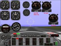
The first screenshot shows the stock P51D "Engine Temperature" Gauge and two new Radiator Temperature Gauges for Engine1 and Engine2 on a chilly Autumn day. Note that temperature which starts at 70 degrees Fahreheit has dropped to 58 degrees F and a digital gauge reads the equivalent in Celsius.
Note that all three "Coolant" all look about the same.

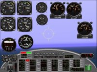
The second screenshot shows the three "Coolant" gauges with the engine fairly warm. Note that the stock P51D gauge isn't really dead but did change slightly. The other two seem to match up pretty well with the digital gauge.

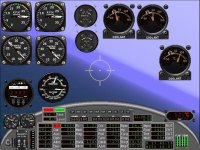
The third screenshot shows the Engine1 "Coolant" gauge showing the engine cooling off after ignition was cut. There are only ignition controls for Engine1 on the test panel.

The new gauge set (at least Engine1 and Engine2) seem to work as expected for -70 C, 50 C, 90 C, and 150 C which takes care of a nagging problem with the stock gauges. They will be included in updates for my panels which currently use the P51D Engine Temperature Gauge.

- Ivan.
 

Attachments

  • ColdEngine.jpg
    ColdEngine.jpg
    125.4 KB · Views: 0
  • HotEngine.jpg
    HotEngine.jpg
    119.3 KB · Views: 0
  • Engine1_IgnitionOff.jpg
    Engine1_IgnitionOff.jpg
    119.8 KB · Views: 0
Late Model P-47 Fuel Gauge

Hello All,

When working on updates to the P-47D-25 that has been stuck in Ivan's Workshop for a while, I came across a very slight problem.
The stock P-47D fuel gauge is appropriate only for the early models of the Thunderbolt up through about the P-47D-23.
Those models of the Thunderbolt had Main Fuel Tank of 205 Gallons capacity.
Later models of the Thunderbolt starting with the P-47D-25 had a larger Main Fuel Tank of 270 Gallons capacity.
The Auxiliary Fuel Tank remained at 100 Gallons.

The stock P-47D fuel gauge is incapable of reading up to 270 Gallons, so it will be necessary to program a substitute gauge.

The stock gauge is rather simple with a Background and two Pointers: One for the Auxiliary Tank and one for the Main Tank.
The proper way to program this gauge is to also have a Mask but for a first attempt, I will try to keep things as simple as possible and use simpler Bitmaps and avoid using the Mask at all.

The Second attached image is the stock P47D Fuel Gauge Background at 3X actual size.
It is pretty obvious that the quality of the image is not particularly good.

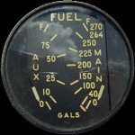
The First attached image is of an actual 270 Gallon P-47D Fuel Gauge in reduced size.
The original photograph of this gauge will be the reference image to create a bitmap.
At the reduced size typical of gauge bitmaps, some of the details of the original image would need to be simplified so that they are still readable at reduced size.

What needs to be avoided is getting hung up on creating detail in the bitmap that will not be visible in use.

- Ivan.
 

Attachments

  • Stock_FuelBG_Big.BMP
    84.9 KB · Views: 1
  • P47D-FuelG-270.jpg
    P47D-FuelG-270.jpg
    61.2 KB · Views: 1
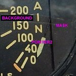
Here is a close up view of the Pointer for the Main Fuel Tank.
It can be seen from this view why there really SHOULD be a Mask included in this gauge.

The code for a two pointer gauge is easy. Any of the Twin Engine Tachometers or Manifold Pressure Gauges can supply the starting point with not a lot of actual code changes inside.

The code for a single pointer gauge with a mask is also pretty easy. The German Fuel Gauge used for the BV 141B can be used as a starting point.

Adding just one more piece isn't all that difficult, but does increase the potential for screwing something up.

- Ivan.
 

Attachments

  • Thunderbolt_Fuel_Gauge_Detail.jpg
    Thunderbolt_Fuel_Gauge_Detail.jpg
    52.7 KB · Views: 5
Duplicate of Stock P-47D Fuel Gauge

I figured the easiest way to program the gauge I wanted was to first program a duplicate of the stock P47D fuel quantity gauge and then change the markings to match the 270 Gallon version and make adjustments.
As I have commented before, the programming is generally fairly easy.
Creating the Bitmaps is the hardest part and I was intending to use the stock gauge's bitmaps to sav time.

The problem though was that the stock bitmaps are VERY small and hard to see, so I figured I would expand them to 3X original size and work with those. The original background is 97x98 pixels.
When expanded, the Lettering and Tick Marks looked even worse and nothing quite lined up, not even the Screws.
After a couple hours trying to fix things, it made more sense to just replace everything, so only the general appearance of the gauge and general location of the tick marks is the same.

I also found a gauge I had done earlier that had two pointers and a mask, so the programming was likely to be pretty easy.

After a couple days of editing, I finally finished the Bitmaps and Code Edits. Another half day of fixing stupid mistakes, and I now have an duplicate of the stock P-47D Fuel Gauge.

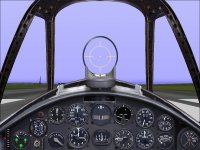
The attached screenshot shows the display at 60% Fuel Load.
Note that the Aux Tank is showing 60% of 100 Gallons or 60 Gallons while the Main Tank is showing 60% of 270 Gallons or 162 Gallons and not 60% of 205 Gallons.

Next step is to modify it to create a 270 Gallon Fuel Gauge.
I had already done the Background for the 270 Gallon Gauge but can't seem to figure out what happened to it.
It appears that all the BMP files in a directory I was working in just disappeared when I renamed the directory.
Nothing ended up in the Recycle Bin.

- Ivan.
 

Attachments

  • NewPanel.jpg
    NewPanel.jpg
    93.1 KB · Views: 7
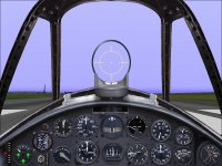
New Gauge is complete.
162 Gallons in the Main Tank (60%) has quite a different appearance.

- Ivan.

P.S. Just noticed that the "0" in "270" was covered by the mask. The number was scooted about one digit to the left and it looks better now. Not worth another screenshot because I am sure we will see it again soon.
 

Attachments

  • NewGauge.jpg
    NewGauge.jpg
    92.9 KB · Views: 6
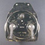
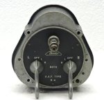
Type B-5 Dual Magneto Switch

Right after I finished the Fuel Gauges for the P-47, I was bit encouraged by the fairly rapid progress.
In the next day and a half, I created a full set of bitmaps for a Type B-5 Dual Magneto Gauge.

The programming behind the B-5 Gauge will be a bit more complicated than the others but will be based on a combination of the Hurricane Magneto Switches and the P-51D Magneto Switches that were done earlier.
The issue right now is trying to figure out the optimum set of mouse areas for the gauge.
Note that there are three separate switches on the gauge face of the B-5 Gauge.

The B-6 Gauge appears to be very similar to the B-5 but instead of a ON-OFF Toggle for the Master Switch, it uses a ON-OFF Push-Pull Knob.

- Ivan.
 

Attachments

  • B-5.jpg
    B-5.jpg
    61.5 KB · Views: 1
  • B-6.jpg
    B-6.jpg
    43.9 KB · Views: 1
Hello Ivan:wavey:

I've been trying, twice in fact, to post but, despite my best efforts, SOH keeps logging me out.

So this is kind of a test as well.

Best way to work on any gauge bitmap is to make it large and hope the algorithms of the paint program you use are up to the resizing/aliasing/color depth palette processes. Saint Paint does a pretty decent job most of the time and I'm sure GIMP would be up to the task as well.

I really envy your talents in the dark art of gauge programming...:redfire:

Hubbabubba

P.S.- It worked!!!
 
Last edited:
Hello Hubbabubba,

Actually, I find that working with an image that is radically different in size from that of the final version often causes problems because it tends to be unpredictable about where the compressing happens.
In GIMP, there is the option of None, "Linear", "Cubic" or "Sinc / Lanczos3" when Scaling an Image.
I find when scaling an image smaller, "None" seems to work best because it doesn't introduce new colours that can get changed into something else when trying to fit back into a particular palette. Anything else tends to eliminate hard lines and everything becomes blurry.
When scaling larger, "Linear" seems to work pretty well but it is very seldom that I start with a small image and try to make it larger.
Another problem is sometimes there is an unpredictable loss of symmetry when scaling an image to a different size.

I like to have perfect symmetry because it lets me set a center of rotation for the needle without trying to remove a wobble that sometimes present with the SDK gauges.

All the concern for precision doesn't actually show up on the panel as you can tell by expanding the screenshots I have posted, but I know that they were as good as I could make them.

What I actually know about programming Gauges isn't really all that much. There are still a bunch of issues that I am having with Fuel Selector Gauges but as with designing using AF99, with each new project, I learn a bit more.
About half my time with these last few gauges has been spent going back and making corrections to prior projects.
Some of it was a lack of any standard solutions in the beginning and some was just making a LOT of non-critical errors just by being in a hurry and being sloppy. (Forgetting to change comments when renaming files, etc.)

If you are really interested, I can help you get set up to program your own gauges. For me the hardest part is the bitmaps rather than the actual programming.

- Ivan.
 
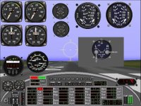
This was the first test of the B-5 Magneto Gauge.
The Mouse Areas appear to work fine.

Some of the logic behind the scenes also needs some debugging.
What happens when the Magneto Switches are moved and the Master Switch is OFF?
What happens when the Master Switch is turned on?

- Ivan.
 

Attachments

  • B5_Test1.jpg
    B5_Test1.jpg
    123.1 KB · Views: 22
A couple hours later, with a few diversions in the middle such as peeling an apple for my Daughter and helping her warm up a snack, the Gauge is done. (At least for Engine1 and Engine2.)

The big ON-OFF Switch will cut all Magnetos if switched off but will not reset the Magneto knob for either engine.
When it is switched on again, it restores the status of the Magneto knobs to each engine.
Perhaps the real gauge works differently. I don't know. I have never actually handled a real one.
If anyone knows that the correct operation is different, please let me know.

The tough part about Gauge Programming is that there is no error checking of the Macros that are expanded to create the C++ code that is compiled to create the Gauge. Thus, if a programmer makes any errors, it may not be so obvious where the actual problem might be, or the error message is very misleading.

Next step is to complete the Gauge for Engine3 and Engine4 to have a pair which is a very simple task.

- Ivan.
 
The Gauge for Engine 3 and Engine 4 is done. It was pretty trivial and really a matter of find and replace in the code.
A Gauge that was conspicuously missing for testing purposes was Starter Switches for multiple engines.
I could only test the starting of Engine 1 easily.
This set of Gauges seems to be pretty trivial (famous last words).

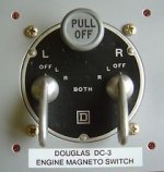
A B-6 Dual Magneto Gauge should be a pretty easy progression from the B-5 that was just finished but I can't quite figure out how to graphically represent a Push-Pull knob instead of the Toggle Switch.
Attached image shows the B-6 Magneto used on the Douglas DC-3.

Another useful visual tool for testing purposes would be a nice 4 Engine Bomber. So far, I have been using my B-25C Mitchell and P-38 Lightning but with two additional invisible engines.
The invisible engines do not make for an easy confirmation that the correct engine is responding to controls.

- Ivan.
 

Attachments

  • Douglas DC-3 B-6 Magneto Switch.jpg
    Douglas DC-3 B-6 Magneto Switch.jpg
    35.3 KB · Views: 22
Sorry if I do not post more often but, as I was saying, I keep being log-off, especially after long-winded post that take me lots of time for back-checking, loading links and image, that sort of things...:banghead:

Of course, I would like to know more!!!

Editing while I have a change;
-Edit size of bitmaps to be in proportion to final gauge;
-Master switch on magnetos' pair was a mechanical-only device, made to "block" magneto in position. I know that because it is obvious in some B-17 training videos. If the bar linking both master switches was down, the "bunny ears" of the magnetos' switches couldn't physically rotate, at least in early models.
-Brits simply used a flip cover on theirs "tits type".
 
Last edited:
Hello Hubbabubba,

On a regular Magneto Switch, if there is a second Magneto Switch, changing one affects the status of the Engine's L&R magneto status and the other switch will reflect what the current status is of the Engine's actual settings. It is strange looking, but flipping one Magneto Switch will cause the OTHER Magneto Switch to also flip to a different setting.

The problem here is that I was seeing the Master ON-OFF Switch as a master kill switch. Thus if it is off, it does not matter if the other individual Magneto Switches are being moved around. At least I don't think there is unless it is internal to the actual gauge.
The engine's actual magneto status needs to be OFF at that point because otherwise it would be able to run, so if the Master Switch is OFF, magneto status is OFF regardless of the position of the other switches on the gauge.
So unlike other gauges, the Magneto Switches on this Gauge do not pick up the Engine's actual magneto switch settings.

Now what happens when the Master Switch is turned ON?
It should pick up the current position of the Magneto Switches on the gauge of course....... Simple, right?
What happens if some OTHER magneto gauge is also changing the engine magneto status?
I am not sure but at this point, I am simply ignoring that possibility because there should not be multiple magneto gauges controlling the same engine on a single panel.

Details about the Gauges:
In general, I try to stay around a 300 x 300 Background Bitmap.
There isn't a real "Standard" Size though I have a few such as 315 x 315 or 303 x 303.
This is a legacy of the bitmap sizes in the FS 98 SDK that I started with.
Its sample gauges were mostly around that size.

The Background for the P-47 Fuel Gauges is actually only 291 x 291.
This is because I started with the stock bitmaps extracted from the P47.gau Multi-gauge but expanded them to 3X original size so that I could have room for lettering. As it turned out, I kept nothing but general arrangement and only a few colours from the stock bitmap, so it really didn't matter.

The Background round section for the B-5 Magneto is also around 300 x 300 but the actual Background is now 525 x 405 because I needed room for the "Rabbit Ears", and the Master Switch sticking out in various directions.

The P-47 Fuel Gauges are specified to be Width 61 because that is what size of the Stock Gauge was. Stock bitmap is 97 x 98 pixels, so my 3X version originally was 291 x 294 pixels but I corrected that to 291 x 291 because the difference was really just 1 pixel in the original. I replaced EVERYTHING anyway, so I should have increased the size of the bitmaps.
If I had increased to 303 x 303, the letters would not be so cramped on the gauge....

The B-5 Magneto is still Width 100 because that is the default width in the FS 2000 SDK and because I have not yet used it in a real panel to get a feel for what size it should be relative to other instruments.

Development Environment is MS Windows 8.1 Operating System Intel Core I7 4th Generation processor.
Compiler is Microsoft Visual Studio 2005.
I found that Visual Studio 2005 can generate code for Gauges that will run on every Operating System as far back as Windows 98 SR2.
I don't run any flight simulators on my Windows 8.1 Laptop, but I know that programs compiled with Visual Studio 2005 will run there because I compile utility programs using the same compiler.
My Windows 98 Desktop Development Machine only has GNU C and the version of compiler it is using is not object code compatible with Windows 8.1.

Hope that addresses most of what you are interested in.

- Ivan.
 

Now look at the cut-off of the engines, starting with #2 and 3 while taxiing at 23:27.

Ignition (all) off at 24:52.

But master only switched-off quite later.
 
Back
Top