Gauges for Combat Flight Simulator

Hello Hubbabubba,

Keep in mind that the kind of Magneto Switch installed may have varied from one version of the aircraft to another.
What is in the film is one of the earlier B-17s, probably B-17E or B-17F.
There were also several four engine versions (which I am NOT planning to build).
One of them had the Magneto knobs going in all four directions from the gauge.

The real potential killer as I see it from a gauge programming standpoint will be the fuel selector setup with crossfeed as found on the P-38 series. I still have not figured out a few issues with fuel selectors for some of the non-FS 98 tanks yet. It obviously CAN be done but *I* don't know how to do certain things.

- Ivan.
 
Minor Variant of Fuel Gauge

One of the things that has bothered me for a while is that there was no "Reasonably Appropriate" Fuel Gauge for the A6M Series panels that I had been working on. The A6M2 had about 145Liters in its Fuselage Tank and 195 Liters in its Wing Tanks but the only stock metric gauges were from the Bf 109E (400 Liters) or FW 190A which was also in the same range.

I had programmed a gauge for the BV 141B-0 which was of 550 Liter capacity.
I figured that redoing the gauge for around 200 Liters capacity (actually 220 Liter limit) would be pretty easy.
The later model A6M3 Model 32 had 205 Liter Wing Tanks and even later versions had combined Wing and Aux tanks of a bit larger capacity which I may address later or not address at all. (Some of these tanks may not have had gauges installed.)

As usual, the Bitmaps (Only the Background this time) was the hardest part.
The tick marks took a couple of tries because I apparently cannot do simply math properly at times.
In about two hours from the start (with some corrections to the original 550L Gauge for default size), I had a working gauge suitable for the A6M2.

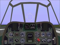
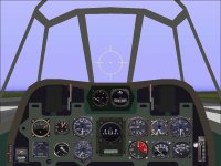
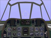
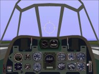
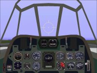
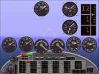
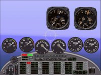
Attached are screenshots of the Panel before and after. The Fuel Quantity Gauge is in the Upper Row left side of the panel.
The original gauge is from the stock FW 190A.
The panel isn't really entirely accurate. The actual GaugeS are on the left console and have separate gauges for each tank.
The position occupied by the Fuel Quantity Gauge was actually used for a EGT gauge for fine tuning mixture for best fuel consumption.

- Ivan.
 

Attachments

  • Stock_Instruments.jpg
    Stock_Instruments.jpg
    73.1 KB · Views: 2
  • 200L_FuelGauge.jpg
    200L_FuelGauge.jpg
    72.9 KB · Views: 4
Hurricane Style Fuel Selector

A couple days ago, I decided I would finish up the "Hurricane-Style" Fuel Selector I had been working on.
The last thing that was really difficult was the pointer. I decided to model my version after the one used on other Hawker aircraft such as the Typhoon / Tempest series.

Folks might be wondering: Why create what is essentially a duplicate of the stock Hurricane Mk.I Fuel Selector?
Reasons are the following:
1. I don't know if others have the same problem, but I have trouble seeing the direction the selector is pointing on the stock gauge.
2. The Hurricane_1 Gauge cycles in one direction. This is a knob that only rotates in one direction and one has to possibly pass through other positions to get to the intended position.
3. The markings do not make sense. There is a "Reserve" position marked but it is not selectable. The British would not have shown a "Center" Tank. Their spelling would have been "Centre".
4. As typical of the stock gauges, the graphics are quite poor quality. They are perhaps sufficient for the scale of the typical panel, but up close, they are a mess.

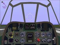
This is a simple three-position fuel selector, so I was VERY surprised when I literally had a stray pointer as shown by the first screenshot. Note that although the gauge is located properly in the A6M panel, the Pointer seems to have escaped and is hiding at the upper left corner of the screen.
The interesting thing is that the point reflects the status of the selection on the gauge and the gauge responds to mouse clicks.

I did a line-by-line code comparison of the broken gauge with the original it was copied from that was presumably working and could not find any obvious problems in the areas I checked. I also compared the code against the L-R Two Tank selector that was done for the Airacobra which I KNEW was working and could still find no obvious problems.
Eventually, I just scrapped the code and started over with the Airacobra Fuel Selector.
The second try worked without a problem.

There are actually very few files involved, so at some point, I will go back and do a comparison between the current working version and the broken version. In theory they should be the same though obviously they are not.
(Besides the Makefile used to drive the program compile, there are only about 4 source files besides the bitmaps.)
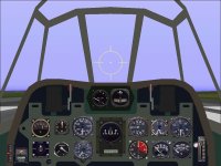
The second screenshot shows the new working gauge.

- Ivan.
 

Attachments

  • BrokenFuelSelector.jpg
    BrokenFuelSelector.jpg
    76.2 KB · Views: 3
  • WorkingFuelSelector.jpg
    WorkingFuelSelector.jpg
    73.3 KB · Views: 2
Naming Conventions

Recently after resuming a bit of Gauge Programming to create a Russian Magneto Switch for the Lavochkin fighters, I discovered that I could not locate the build directories for a couple P-47 Fuel Gauges I had done VERY recently.
I almost got to the point where I was considering building them again until I went through this thread and found how recently they had been done (March 2020).
It seems that with those two Gauges, my naming convention was a bit inconsistent and they just were not where I expected them.

For duplicate CFS Gauges such as the P51D Coolant Temp Gauge, the hierarchy is CFS-Aircraft-GaugeType.
For my own newly created Gauges, the hierarchy is KPW-GaugeType-Specifics where specifics may be Aircraft, Nationality, or something else uniquely identifying. The point is that All Fuel Gauges were expected to be in a group and these were not.
I still need to go back and correct that.

The Russian Magneto Switch isn't quite as straightforward as a direct copy of code from the CFS P51D Magneto I had done earlier. The ordering of the switch positions is different.
Now that it is done, its code seems to be directly compatible with a Japanese Magneto Switch.
I just need to find some clear images of what the markings are on the face of that Gauge.

- Ivan.
 
Japanese Magneto Switch

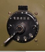
The positions on the Russian Magneto appeared to be the same as those for the Japanese A6M.
Yesterday was spent trying to find the markings to put on the face of the Japanese Magneto.
This turned out to be a much more difficult task than anticipated.
Most images of the Gauge are so small that the writing is unreadable.

Eventually I found a reasonable photograph which is attached.
Anna Honey helped me translate the markings so that I could get them lettered properly on the Gauge face.
Although the originals are rotated to match the switch alignment, I found that rotating the Kanji made it pretty much unreadable, so that is a detail I will not try to reproduce.

The programming changes were not particularly complicated but I finished up so late that I did not have a chance to test and get screenshots. I will post screenshots when I can.

-------

The next Gauge project will be a fairly simple one. It will be a set of multi engine Starter Switches.
The question is what appearance the switches should take.

- Ivan.
 

Attachments

  • Image.jpg
    Image.jpg
    33.9 KB · Views: 22
Just finished updating the panel on a "Throw-away" A6M3 Test Aircraft.
This is the same aircraft that was used to test the vertical CoG change a few months ago.
It is a "Throw-away" because although its visual appears correct inside the simulator, its entire model was moved via SCASM edits and will not show up correctly in programs such as DPEdit that read the actual MDL code.

Three Gauges have been replaced in the panel since it was last edited.
The Fuel Gauge was from the stock FW 190A and is now a custom 250 Liter Gauge.
The Fuel Selector was from the stock Hurricane Mk.I. The new Gauge has a similar appearance but allows the knob to turn left or right instead of forcing a cycle through all three positions.
The Magneto Switch is new and at this point only Engine1 has been tested here.

Of the three Gauges, I am really satisfied with only one: the 250 Liter Fuel Gauge.
The other two have no functional, but do have slight appearance issues that I believe need addressing.

- Ivan.
 

Attachments

  • A6M3-22X.jpg
    A6M3-22X.jpg
    49.9 KB · Views: 1
  • OldGauges.jpg
    OldGauges.jpg
    73.8 KB · Views: 1
  • NewGauges.jpg
    NewGauges.jpg
    73.3 KB · Views: 3
Lavochkin Panel and Gauges

Recently I have been trying to update my La 5FN that was originally built back in 2003.
At the time I worked on that project, I wasn't very concerned with setting up a proper panel.

The main objective was to build a nice looking visual model without significant bleeds.
I also didn't know much about flight modelling at the time so all I really tried to do was get the basic geometry of the airframe and engine correct and try to tune for maximum speed.

When NoDice wanted to host some of my projects at his site, I had no objection. I was also not surprised to see that he chose to substitute Panels and Gauges by MoparMike because all I had done was to alias the La 5FN panel to that of the stock P-47D.
Recently I decided to actually look at what the replacement panel looked like and I am amazed.
It isn't perfect, but it is much better than anything I am likely to achieve any time soon.

- Ivan.
 
Japanese Magneto and Panel Updates

Attached is a screenshot of the updated panel for the A6M3 Test Aircraft.
It now incorporates all the current gauges I have for the A6M series.
The newest gauge is a Japanese Magneto Switch.
The Japanese MP gauge replaces the CHT gauge which is moved to the right side.
The difference between versions of this panel the fuel gauge because of the different fuel capacities between different models of the A6M.

The only thing really conspicuously missing at this point is a proper Air Speed Indicator.
The one on the A6M should read in Knots instead of KPH.

- Ivan.
 

Attachments

  • JapaneseMagneto.jpg
    JapaneseMagneto.jpg
    73.1 KB · Views: 21
Gauge Sets

About a month ago, I was looking through the Gauges Directory of my Development Machine.
I was looking at a downloaded aircraft that seemed to have an incomplete set of gauges and I did not actually find the gauge that was missing from the PANEL.CFG of that aircraft.

In looking through the directory, I found quite a few gauges that might be useful, but I also found many partial sets of gauges in which there was instrumentation for three engines but not four or just two engines when a full set of four would have been quite useful.

With single gauges these were obviously FS98 types, but I still can't imagine an author not spending the additional half hour necessary to create a full set for four engine aircraft even if he doesn't need it. I just wonder what may have happened to the others in the set.

With the FS2000 SDK that I am currently using, EVERYTHING is a library or SET of Gauges.
The question is just what the designer (in this case, Me) chooses to put into the set.

Some folks (notably M$) choose to put in all the gauges related to a particular aircraft.
I am not sure how well that works when there may be several variant of an aircraft such as with the Mustang or Thunderbolt. Both had different configurations of fuel tanks depending on the model and a fuel selector or fuel quantity gauge for one model may not be appropriate for another.
Early Mustangs did not have a fuselage fuel tank and Thunderbolt fuel tanks varied in size.
Even with the FW 190A, some models had three fuel tanks and some only had two with a MW50 tank.

So far, my choice has been with most non-engine gauges has been to do singles even in a library.
With engine gauges, where it makes sense and where I didn't get too lazy, I have been doing full sets for four engines even though I haven't work on anything with more than two engines.

Anyone care to give their thoughts as to whether this idea makes sense or is there a better one?
(Still refining best practices.....)

- Ivan.
 
3 in 1 Engine Gauge

Gauge Backgrounds are almost always the worst part of constructing a new gauge.
That is why about a half dozen gauges I have programmed thus far have used either the stock Microsoft Gauge images or slightly modified versions of them.

With the Backgrounds and Pointers already completed, the task of programming to complete the Gauge doesn't seem quite as daunting and gets done faster. This time, I am taking a slightly different approach.
The Background and other images for the "3 in 1 Engine Gauge" are quite small and poor quality. I magnified each image to be approximately the size of the image I would use if I were starting from scratch and just made corrections by hand. The results are not great, but good enough and the sizes are such that there will be minimal code changes when I create better images to use for a new gauge.

The original unmodified gauge is shown in the upper right in the attached screenshot.
The multi engine gauges show that at least some of the coding should not be difficult.

- Ivan.
 

Attachments

  • DualOilTempTest.jpg
    DualOilTempTest.jpg
    118.1 KB · Views: 17
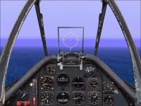
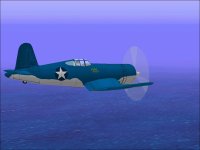
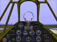
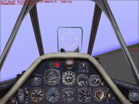
Fuel Gauge - F4U Corsair

Here was a minor diversion from the last project.
The Bitmaps took a day or so after I figured out it wasn't such a great idea to actually copy the tick marks on the original gauge which are arranged in a somewhat odd pattern. The gauge is installed on the lower right of my "Corsair" panel.

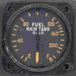
The first image is one of the actual gauge.
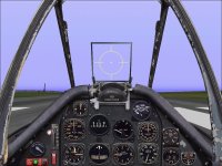
The Second is the installation in the panel of a F4U-1A (With outboard wing tanks) which explains the fuel selector.

Note that the Fuel Selector is mine rather than the one from the P51D.

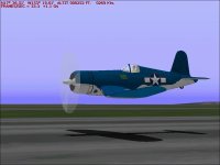
The Third screenshot is just the -1A Corsair which could use a few updates.

- Ivan.
 

Attachments

  • Vought-F4U-Corsair.jpg
    Vought-F4U-Corsair.jpg
    12.1 KB · Views: 3
  • Corsair_FuelGauge.jpg
    Corsair_FuelGauge.jpg
    96.6 KB · Views: 3
  • Corsair_LowPass.jpg
    Corsair_LowPass.jpg
    41.5 KB · Views: 2
Navy Fighters

One of the amusing things about panels for Navy fighters for Combat Flight Simulator is that the ones I have encountered tend mostly to have Air Speed Indicators calibrated in MPH instead of Knots. Since I don't happen to have a ASI reading in Knots, I thought I would try to address this issue.

This is the result for a first attempt. There are still some issues that need to be addressed.
The background is derived from the stock P51D Airspeed Gauge and the result did not turn out as good as I had hoped.
Now that the programming behind the scenes is mostly done, creating a new Background seems to be less of a chore.
It is more a case of instant gratification once it is done rather than having more tasks after that.

For now, this Gauge will do until I can finish a replacement.

- Ivan.
 

Attachments

  • Airspeed_Indicator.jpg
    Airspeed_Indicator.jpg
    97.5 KB · Views: 5
  • TrimmedForCruise.jpg
    TrimmedForCruise.jpg
    45.3 KB · Views: 3
P-40N Panel Updates

This morning I decided to update the panel for my P-40N by replacing the FW190A fuel selector with the one programmed specifically for the P-40N.
I don't know that the appearance is improved, but the gauge looks more like the real thing.
The other gauge that is not a stock gauge is the Radiator gauge. This one actually works like it should.
The P-40N is awaiting new propeller tables before a re-release. At the moment, there are no extra technicians available to work in that area.

The reason why this Fuel Selector is specific to the P-40N is that although just about every model of P-40 had the same three internal fuel tanks, the naming of the tanks between models was not consistent and markings on the Fuel Selector would have been different.

The reason for this slight diversion is that I am currently working on a Fuel Selector for the FW 190D and from a logic standpoint, a lot of the code will be lifted from what I did for the P-40N Fuel Selector. This is often how it works with gauge programming. Two gauges that have nearly no resemblance to each other are quite similar from a programming standpoint.

- Ivan.
 

Attachments

  • P40N_PanelUpdate.jpg
    P40N_PanelUpdate.jpg
    97.1 KB · Views: 5
  • P-40N_Portrait.jpg
    P-40N_Portrait.jpg
    51 KB · Views: 4
FW 190 Fuel Selector

Attached is a screenshot showing the new two position FW 190 style Fuel Selector.
This functionality was already available in the stock P47D Fuel Selector but the appearance wasn't quite right for a FW 190D.
There is also a three position version in the same set just for completeness.

None of these recent Fuel Selectors that extend beyond the FS98 Fuel Tanks is completely correct but they are good enough to get the projects that need them moving. They will be improved whenever I learn how to do it.

- Ivan.
 

Attachments

  • UpdatedDoraPanel.jpg
    UpdatedDoraPanel.jpg
    91.6 KB · Views: 10
P-38 Lightning Fuel Gauges

The Bitmaps for this Gauge set were pretty typical and took a couple days to create.
The programming for the gauges took well over a week which is pretty unusual for a set of fuel gauges.
There were two basic problems. One was very poor and incomplete documentation in the SDK. The other was that I managed to goof very very slightly when copying the code for the Main Fuel Gauge to the Reserve Fuel Gauge.

The Reserve Fuel Gauge kept indicating the same as the Main and that did not make sense.
All the variable declarations looked correct but the gauge still did not behave correctly.
I finally decided to comment out the code for the Main gauge to see what would happen.
The compile failed with an undeclared reference in the Reserve gauge code..... It was undeclared because it was using a variable from the Main gauge code which was no longer being included.

The attached screenshot shows the gauges being tested in a twin engine aircraft with fuel tanks configured the same as on the typical P-38 without tip tanks.

The fuel for the Left Aux tank (which represents the Lightning's Left Main) has been dumped.
The Left Main tank (which represents the Lightning's Left Reserve) obviously has fuel being drawn as does the Right Aux tank which represents the Lightning's Right Main.
Without a fuel selector, this is the best configuration to use because the default fuel usage will be the recommended order.

- Ivan.
 

Attachments

  • P38_FuelGaugeSet.jpg
    P38_FuelGaugeSet.jpg
    105 KB · Views: 8
P-51D Three Way Engine Gauge

This Gauge was finished and tested last night.

The attached screenshot shows the new Gauge (on the Left) as compared to the stock P51D Three Way Engine Gauge.
As can be seen, the readings seem to be pretty much the same which is a pretty good indication that the programming was correct.

Comparing the readouts against the Test Panel's digital gauges does show something quite interesting though.
There are three values being displayed here:
1. The Oil Temperature. 171 degrees F converts to 77.22 degrees C which is a pretty good match.
2. The Oil Pressure. 59 PSI also seems to be a pretty close match to the new gauge.
3. The Fuel Pressure. The Test Panel shows 22 PSI but both P-51 Gauges show about 16-17 PSI.

If the discrepancy were just in my new Gauge, I would be a bit worried, but my readings match the stock gauge.....

The bitmaps for the new Gauge started as stretched copies of the stock P51D images, but almost nothing but the Gauge Frame and some of the Tick Marks remain of the original.
The Numbers have all been redone.
The Pointers are all new.
The Tick Marks have been moved around so that the Gauge Pointers are symmetrical.

Eventually the Bitmaps will probably be entirely replaced, but this seemed to be the quickest way to get a working gauge for now.
So far I have just a Gauge for Engine1.
Creating the full set of four Gauges for all four engines should not be terribly difficult.
I will need at least two for the P-38 Lightning.

- Ivan.
 

Attachments

  • 3WayEngineGauge.jpg
    3WayEngineGauge.jpg
    104.9 KB · Views: 12
A Couple Weeks Later.....

After a couple weeks of workigg mostly on Gauges, I now have the following additions:
Dual Pointer 4500 RPM Tachometer
A set of Cylinder Head Temperature Gauges based on a modified stock P47D bitmap
A set of Starter Gauges based on the stock P51D bitmaps

Many Gauges that were already completed were improved a bit for accuracy or logic based on what I found when looking for information to program the new Gauges.

The first try at a set of P-38 Fuel Selectors had multiple problems.
Most have a known solution but there is one issue that still eludes me.

One other Gauge is in the works but it is moving slowly and still in the bitmap stage.

- Ivan.
 
More Gauges for Lavochkin

Two more Gauges are now finished for the Lavochkin fighters.
As expected, the Manifold Pressure Gauge was pretty trivial.
Other than the markings, it doesn't differ much from other Manifold Pressure Gauges.

The 2 pointer Tachometer took a much longer time.
Eventually I got some help about a very non-intuitive problem with the way I was doing things and last night, I finally got everything to work properly.
Thanks, DragonflightDesign!

Next will probably be a Cylinder Temperature Gauge for the Lavochkin along with another that is slowly working in the background.

- Ivan.
 

Attachments

  • GaugesForLa5FN.jpg
    GaugesForLa5FN.jpg
    117.4 KB · Views: 6
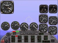
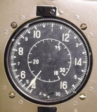
After a rather long break, my old laptop seems to be functional again, so in order to test things out, a new Air Speed Indicator is in the works. It was the one gauge that remained from the stock gauges that the A6M panel was built with.
The Japanese seemed to be really fond of multiple rotation pointers on gauges. I choose not to implement things that way because I believe that without the sensations of actual flying, it isn't always instantly obvious what the readings really should be.

- Ivan.
 
The maximum diving speed of the A6M2 (and other long winged variants of the A6M) was only 340 Knots IAS.
This is only 391 MPH which is fairly low. The interesting thing is that the gauge apparently only reads up to 300 Knots.
As mentioned earlier, the full scale is shown in two revolutions so at times, reading just the dial indicator, it may not be obvious what the actual air speed is: Am I going 120 or 250 Knots?
The CFS2 ASI for this aircraft is a very good replica of the actual gauge with all of the ambiguities.

- Ivan.

A6M-ASI.jpg
 
Back
Top