Lockheed P-38 Lightning - Design Study

Ivan

Charter Member
Recently I had been looking over P-38 Lightning visual models and doing some reworking on an existing AFX by Eric Johnson. I had no intention of re-releasing his work but was using it as a "feasibility" study to experiment with techniques to kill the bleeds which are common to CFS Lightnings. The Lightning is an odd construction and had parts relationships which may require different assembly processes from other Aircraft Factory 99 models.

In doing this, I came across quite a lot of documentation and drawings of the P-38 in various (mostly J &L) models. In doing some quick calculations, it seems that even with my building methods, I MIGHT be able to complete a P-38J project within AF99 resource limits.

It will be close, so all I am calling this is a "Design Study". We shall see if this project ever gets to a releasable stage.

.....

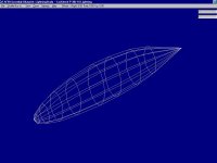
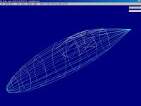
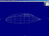
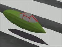
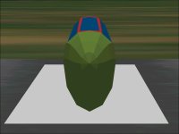
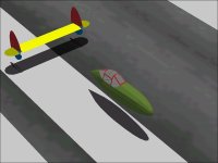
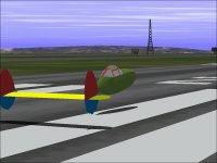
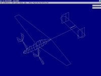
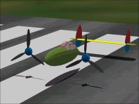
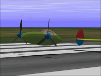
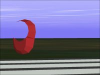
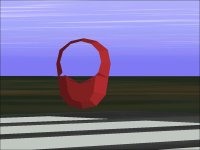
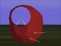
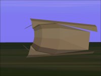
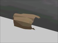
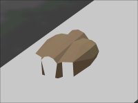
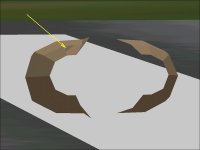
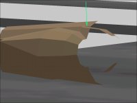
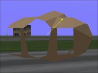
I have always thought that the Nacelle on the P-38 Lightning was not really a pretty much symmetrical cross section from top to bottom but with a section removed ahead of the canopy.

Here are a couple screenshots that should explain my meaning.
 

Attachments

  • Lightning_Pod.jpg
    Lightning_Pod.jpg
    43.7 KB · Views: 0
  • Lightning_Embryo.jpg
    Lightning_Embryo.jpg
    70.4 KB · Views: 0
  • Lightning_NacelleTop.jpg
    Lightning_NacelleTop.jpg
    39 KB · Views: 0
Nacelle Screenshots

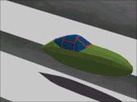
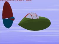
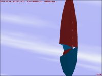
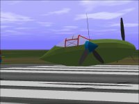
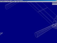
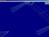
Here are a few screenshots of the Nacelle Assembly in the simulator.

The screenshots also show some revisions to the contours of the canopy frame and glass.
The parts count for just this is up to 172 polygons.
 

Attachments

  • Lightning_Nacelle2.jpg
    Lightning_Nacelle2.jpg
    32.1 KB · Views: 0
  • Nacelle1.jpg
    Nacelle1.jpg
    35.2 KB · Views: 0
  • Nacelle2.jpg
    Nacelle2.jpg
    27.1 KB · Views: 0
  • Lightning_Nacelle1.jpg
    Lightning_Nacelle1.jpg
    31.6 KB · Views: 0
Rudder & Fin

I expected the Rudder and Fin combination to be one of the more difficult areas.
I had expected each side to only need one AF99 Component but needed two per side instead.

Note that each component is a different colour and also note that they are interlaced.
This is similar to the normal practice of interlacing the Canopy Frame and Canopy Glass.

The shape of the Rudder was plotted first.
It was then reversed and stretched and then moved back into alignment to form the Fin outline.
A few points were moved around slightly but the basic forms were done by a program I call "StretchIt".

Each Rudder / Fin is entirely symmetrical from side to side.
One side's Parts were created and then Mirrored.
After Mirroring, the parts were then shifted 16 feet (each engine is 8 feet from aircraft centerline) to match the original pieces.
 

Attachments

  • Lightning_Rudder1.jpg
    Lightning_Rudder1.jpg
    40.9 KB · Views: 0
  • Lightning_Rudder2.jpg
    Lightning_Rudder2.jpg
    26.5 KB · Views: 0
  • Lightning_Rudder3.jpg
    Lightning_Rudder3.jpg
    34.5 KB · Views: 0
Horizontal Stabiliser

The fancy intersection between the upper and lower parts of the Fin assembly are pretty much hidden by the Horizontal Stab.

The end of the Boom on the Lightning where it meets the Tail Assembly is 13 inches high and 10 inches wide. I shifted the joint about 4 inches Aft and made the cross section a fraction of an inch smaller in each direction.

Note that the cross section at the end of the Boom is only 8 sided. More is a waste because the pieces are so small and also because I am sure to run short of AF99 Parts later.
 

Attachments

  • Lightning_NewStab1.jpg
    Lightning_NewStab1.jpg
    36.2 KB · Views: 0
  • Lightning_NewStab2.jpg
    Lightning_NewStab2.jpg
    54.9 KB · Views: 0
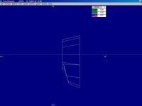
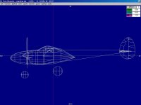
Templates & Jigs

Creating the Templates and Construction Jigs has taken the most time.
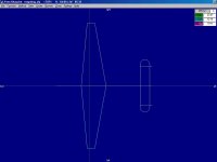
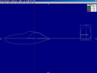
The shapes in these screenshots seem to be very simple but contain quite a lot of information.

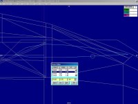
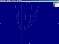
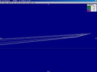
From the Side View:
The Center of Gravity of the Visual Model is located.
It is 13.00 feet behind the Forward Tip of the Nacelle.
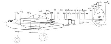
The tip of the Nacelle represents "Station Zero" in the technical drawings of the aeroplane. All Horizontal Longitudinal Offsets are from this point.
The Horizontal Line is the "Fuselage Reference Line" that is the reference for Vertical Offsets in Tech Drawings.
Note that the Vertical Center of the model is a bit above this. The Vertical Center coincides with the Engine Thrust Line at 5.078 inches above the FRL. This was determined by Loading Diagrams which located the Aircraft CoG with Landing Gear Down and Landing Gear Up.
5.078 inch is 0.42316666 Feet which is rounded by AF99 precision to 0.42 Feet.
Landing Gear Position shifts the CoG slightly both Verically and Longitudinally as would full or empty fuel tanks. The Visual Model's center falls within the actual aircraft's CoG range with these variations.

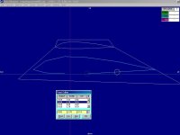
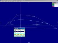
The Wing Template shows the Root and Tip chords as well as the angle of incidence at the root and the dihedral. Note that the Wing actually has Washout that is visible from the tip.
The Incidence at the aircraft centerline is 2 Degrees and the Wing is rotated about Station 160 (160 inches from the Nacelle Tip).
The Incidence at the Wing Tip is Zero Degrees.
Also shown is the Wing Leading Edge and Trailing Edge sweep angles. LE Sweep is 5 Degrees 11 Minutes 31 Seconds.
In reality, we are quite not that accurate, but this template is as close as we can get in AF99.

I did not post a Frontal Screenshot but it shows the Wing Dihedral which is 5 Degrees 40 Minutes.
In reality, the Dihedral is a touch less than this because although the Wing is assembled with that amount of Dihedral, Dihedral would decrease slightly as the wing is rotated 2 degrees incidence after assembly.

The Side View also shows the Stab Vertical Offset at 21.099 inch above the FRL.

Top View shows the Stab Leading Edge at Station 397.584, Stab Span at 261 inches and Stab Chord at 45 inches. Elevator Chord is 20 inches which is not shown in these templates but is reflected in the AF99 Component polygons.

The entire Tail Assembly is rotated 1.25 degrees Nose Down in Pitch but that will not be reflected at all in this model.

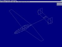
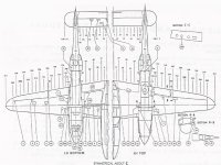
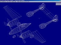
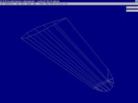
The 3D View shows the alignment of the Fuselage "Bulkheads" or Frames and how they relate.

- Ivan.
 

Attachments

  • Lightning_TempSide.jpg
    Lightning_TempSide.jpg
    25.5 KB · Views: 0
  • Lightning_TempTop.jpg
    Lightning_TempTop.jpg
    23.9 KB · Views: 0
  • Lightning_Temp3D.jpg
    Lightning_Temp3D.jpg
    30.6 KB · Views: 0
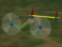
Propellers and Spinners

The Propeller Arc on the Lightning is located at Station 61.875
The Propeller Diameter is 11 feet 6 inches.
The Propeller Pitch Range is 23.0 Degrees to 57.7 Degrees with 87.5 Degree angle when Feathered.
The Reduction Gear Ratio is 2:1.

The Tip of the Spinner is located at Station 44 1/32
The Base of the Spinner is located at Station 67.5

The Master Propeller Blade was created with Zero Pitch and then Rotated in Yaw -26.57 Degrees (Why did I pick that angle?) and then the points were adjusted to make them all be as aligned as possible.
The Top Blade I saved as PropBlade1L. I then rotated the Master Blade 120 Degrees and Save it as a second blade and 240 Degrees for the remaining blade. The Right Side Propeller Blades are simply mirrored from the Left Side Parts because the Propellers rotated in opposite directions.

I could not find the diameter of the Spinner, so it is pretty much a guess based on the Spinner from the P-40 Warhawk.

The Front Half of each Spinner is located in either the Right Nose or Left Nose in AF99 along with the Prop Blades from that side.

The very surprising thing that can be seen in the screenshots is that there appear to be no bleeds at this point even though I had expected some interactions with the Nacelle.

Parts Count is now 442 of 1200 possible.

- Ivan.
 

Attachments

  • Lightning_Propellers.jpg
    Lightning_Propellers.jpg
    34.2 KB · Views: 1
  • Lightning_Propeller1.jpg
    Lightning_Propeller1.jpg
    44.7 KB · Views: 0
  • Lightning_Propeller2.jpg
    Lightning_Propeller2.jpg
    51.4 KB · Views: 0
  • Lightning_Propeller3.jpg
    Lightning_Propeller3.jpg
    49.7 KB · Views: 1
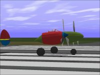
Propellers and Wheels

532 Parts of 1200 Allowed.

Since last time Propeller Blurs have been added.
The Propeller Animation is through Aircraft Animator.
The Transparent Disk is handled a bit strangely in AA:
The Propeller Diameter is 11.5 feet. As expected, the Propeller Blur is the same Diameter.
Converted to Metric as used in Aircraft Animator, this would be 1.7526 Meters Radius.

The strange part is that although Aircraft Animator gives a default selection for the radius of the Transparent Disk, it actually allows much more precise changes though it will not save them after generating the model.
AA gave a default of 1.8 Meters radius. I found that 1.78 Meters was a better match for the Propeller radius as can be seen in the screenshot.

Also added were Wheels.
The Nose Wheel is 27 inches in diameter.
The Main Wheels are 36 inches in diameter.
The main wheels are each 99 inches from the aircraft centerline (Track is 198 inches).
The wheel base is 120.831 inch.

I could find no information on the width of any of the tyres.
I also cound not find information on the angle of either the Main Gear Struts or Nose Gear Strut.
The locations in this model are scaled from the most reasonable drawing I could find.
The distance between wheel centers in the model is 120.265 inches which is fairly close but does not account for wheel diameters.
There obviously may also be some error in scaling from the drawings which were really a "best guess" and isn't too bad when considering that the error is less than the width of a line in the drawing.

The AIR file required a 4 inch vertical shift for each Landing Gear Contact Point but doesn't really take into account that the actual aircraft is quite heavy and compresses and flattens the tyres quite a lot. The wheels start as a 10 sided shape and are rotated so a flat is at the bottom but this still does not come close to matching the appearance of a weighted tyre.

Lots more pieces to make.
- Ivan.
 

Attachments

  • Propeller_Animation.jpg
    Propeller_Animation.jpg
    32.6 KB · Views: 0
  • Wheel_Contacts.jpg
    Wheel_Contacts.jpg
    48.3 KB · Views: 0
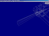
Cowl Panels

Here are a few screenshots along with a picture of the current wire frame of the front of the Lightning's Cowling.

The points are scaled from a drawing with some minor adjustments by eyeball to line things up better.
As is typical with an Engine Cowling, the panels are all pretty much smooth curves.
We approximate curved lines with points and straight lines so where we pick the points is by "artistic" interpretation. It helps to pick points so that the lines connecting them will align well with the shape of the aeroplane.

Note also that although this is an Allison engine as on the P-40 Warhawk, the Cowling is much wider.
The exhausts on the P-40 are outside the Cowling panels.
The Lightning's exhaust manifolds are INSIDE the cowling because the exhaust gas is piped to the Turbocharger in the Boom on top of the Wing.
The maximum width of the Allison V-1710 is a bit over 29 inches (from one of the Jane's books). With the required ducting on the sides, my estimate of the width was 44 inches which was a fraction of an inch over the number I got from scaling a drawing.

As can be seen from the screenshots, one of the polygons is not quite flat enough; it disappears when viewed from certain angles. It will need to be adjusted.

I also cheated a little bit to make the Cowl and Boom easier to build:
It is being built on the centerline of the model rather than offset 8 Feet to the Left. This makes it much easier to mirror a part from one side to the other for symmetry.

Shifting everything to align with the Engine Thrust Line at the end will be trivial.

- Ivan.
 

Attachments

  • CowlFirstTry1.jpg
    CowlFirstTry1.jpg
    36.8 KB · Views: 0
  • CowlFirstTry2.jpg
    CowlFirstTry2.jpg
    42.1 KB · Views: 0
  • CowlFirstTry3.jpg
    CowlFirstTry3.jpg
    21 KB · Views: 0
More Engine Cowls

Fixing the non-planar polygon was fairly easy but moved just about everything around a bit.
It also required adding another polygon which probably should have been there initially.

Note that the front face of what will be the Oil Cooler and Intercooler Intake extends into the Spinner Opening.

When the Spinner is in place this will not be visible.
Note also that that some of the lines in the lower Cowl area do not line up as well as they should.

Second Screenshot shows the general arrangement with templates for the Booms.
 

Attachments

  • CowlSexondTry1.jpg
    CowlSexondTry1.jpg
    29 KB · Views: 0
  • CowlSexondTry2.jpg
    CowlSexondTry2.jpg
    37.9 KB · Views: 0
Engine Cowl Fit

These screenshots show how the Engine Cowls fit in with the rest of the Aeroplane.
Each Cowl Component is 60 Polygons so far and does not have any bleeds that I can see.
Total Polygon Count is now at 564 of 1200 allowed.

Note that there are also a few bugs in Aircraft Factory 99 which needed a work around.
The Cowl was assembled on the centerline of the model so that mirroring and matching would be easier.
The problem is that the Cowl / Boom assembly will need to match the Wings on each side. This means that the outside of each Boom will be different from the inside.

To get this assembly, I first added the Cowl Component and shifted it 8.00 feet Left. I added a "Fit to Opposite Side" Cowl and shifted IT to the Right.
The problem is that the "Opposite Side" Cowl did not display properly so I had to add a non "Opposite Side" Cowl for the Right Side.
This works now when just the Cowl is built because it is symmetrical, but the next section which will meet with the Wing will not be symmetrical.

- Ivan.
 

Attachments

  • CowlSexondTry3.jpg
    CowlSexondTry3.jpg
    46.2 KB · Views: 0
  • CowlSexondTry4.jpg
    CowlSexondTry4.jpg
    50.4 KB · Views: 0
Tail Booms

The Tail Booms were extremely simple to build:
The Aft Cross-Section is pretty much a simple Octagon.
The Forward Cross Section is very nearly a simple 12 sided Oval.

Creating the piece is a simple matter of connecting the dots and then creating the Component by adding each Part as a Left-Right Pair.
As before, there is a problem with assembling with an "Opposite Side Part".
Screenshots are attached.
 

Attachments

  • TailOppositeHalf.jpg
    TailOppositeHalf.jpg
    46.1 KB · Views: 0
  • TailMirrored.jpg
    TailMirrored.jpg
    45.2 KB · Views: 0
  • TailNonMirrored.jpg
    TailNonMirrored.jpg
    48.4 KB · Views: 0
Radiators

I had expected the Radiator Fairings to be the most complicated part of the entire Aeroplane.
I believed it was possible to create the Radiator and the section of the Tail Boom that it is mounted on as a single Component.

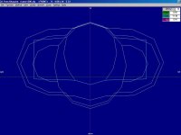
The first screenshots show the cross-sections at the Radiators.
I believe the shapes are reasonably faithful to the actual aircraft, but a lot of it was done "By Eyeball" with just the outside dimensions taken from drawings.
I believe the shape isn't bad though it still needs adjustments mostly on the back end.

The last screenshots show how the piece appears in the simulator.
Obviously there are still a few bleed problems but they look to be easy to fix.

The screenshots show these as untextured "Sharp" Components. When they are assembled as textured "Smooth" Components, a lot of the shading and shadows that are visible here will disappear unfortunately.

- Ivan.
 

Attachments

  • RadiatorTemplates.jpg
    RadiatorTemplates.jpg
    44 KB · Views: 0
  • RadiatorTemplate3D.jpg
    RadiatorTemplate3D.jpg
    57.6 KB · Views: 0
  • RadiatorFirstTry1.jpg
    RadiatorFirstTry1.jpg
    22.8 KB · Views: 0
  • RadiatorFirstTry2.jpg
    RadiatorFirstTry2.jpg
    27.9 KB · Views: 0
  • RadiatorFirstTry3.jpg
    RadiatorFirstTry3.jpg
    26 KB · Views: 0
1200 polygon cap? Damm... Glad I work in CFS2 that has almost no cap but a practical cap of 8000 to 10,000 for the main LOD.

Also made me get off my but and get the stock CFS2 P-38F rebuilt to a P-38J.

View attachment 16281
 
Hi Allen,

Actually the limits are much worse than a simple 1200 Polygon limit would suggest.
The "Practical" limit is more like 1170 but depending on the complexity of the model, weird things may start happening at around 1120 or so, and my models tend to push the limits of what Aircraft Factory 99 will handle.
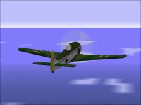
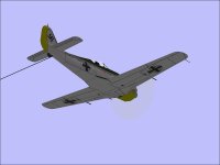
See the attached screenshots for an example of a "Weird Thing" happening.
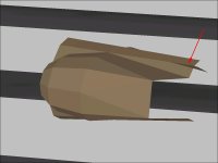
Especially with this model, many of the pieces are built a certain way not because I don't know how to build more detail but because I KNOW I will be very near the resource limit when I am done. There is also the problem that Combat Flight Simulator doesn't handle small textured polygons very well because of how coarse the texture mapping is.
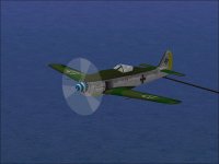
If you look at the order of which pieces I am choosing to build first, it may seem very non-intuitive but I believe it makes sense because I am trying to resolve the nastiest issues first. I don't even know if I will be able to finish this project because of resource limitations. I am up to 828 Polygons with the latest version and that doesn't even count the 100-150 I will need to add in the Nacelle for the Pilot and some minimal equipment.

I also have both CFS2 and CFS3 but have never tried to build anything for them. The original CFS seemed to need more help which is why I originally started building: It was an attempt to prove that fairly nice looking aeroplanes could be built with the most commonly available modelling tools.

When you did your conversion, did you come up with something similar to what I did for the Radiator cross-sections?
P-38 Lightnings are interesting to look at, huh?

- Ivan.
 

Attachments

  • FW190A_OopsHiding.jpg
    FW190A_OopsHiding.jpg
    33.9 KB · Views: 0
  • FW190A_OopsLF.jpg
    FW190A_OopsLF.jpg
    52.8 KB · Views: 0
  • FW190A_OopsRALow.jpg
    FW190A_OopsRALow.jpg
    28.2 KB · Views: 0
Radiator Update

This is the updated Radiator with the aft section slightly reworked.
There are still some bleeds as can be seen in the screenshots, but they are minor enough that I can live with them for now.
There is also a pretty good chance that some of these bleeds will be hidden by the Wing or parts of the Tail.

Although most of the polygons have not changed, the Assembly Order is now something which can best be called "non-intuitive".

Each Radiator is now up to 72 Parts not including the Inlet or Exhaust which should use up another 16 Parts for the pair of Radiators.
 

Attachments

  • RadiatorSecondTry1.jpg
    RadiatorSecondTry1.jpg
    18.4 KB · Views: 0
  • RadiatorSecondTry2.jpg
    RadiatorSecondTry2.jpg
    19 KB · Views: 0
  • RadiatorSecondTry3.jpg
    RadiatorSecondTry3.jpg
    28 KB · Views: 0
  • RadiatorSecondTry4.jpg
    RadiatorSecondTry4.jpg
    26 KB · Views: 0
  • RadiatorSecondTry5.jpg
    RadiatorSecondTry5.jpg
    32.4 KB · Views: 0
Radiators added to Assembly

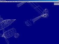
Here is how the Radiators look when fitted to the rest of the Aeroplane.

Total Parts count is now 828 of 1200 allowed.
Aircraft Factory 99 is now complaining that I have exceeded the 800 Part "suggested" limit.

- Ivan.
 

Attachments

  • Update120301.jpg
    Update120301.jpg
    46.8 KB · Views: 0
  • Update120302.jpg
    Update120302.jpg
    48 KB · Views: 0
Wings of the Lightning

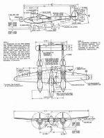
The P-38 Lightning used a NACA 23016 airfoil at the root (Aircraft Centerline) and a NACA 4412 at the tip.
The NACA 23000 series airfoil is pretty common on WW2 era aircraft but the NACA 4412 at the tip is a bit unusual.
The NACA 4412 is highly cambered with a shape somewhat similar to the Clark Y.

From the attached images we can see that:
1. The Wing Tip comes about halfway up the side of the canopy as seen from the side.
2. The upper surface of the Wing continues to the Wing Tip.
3. The lower surface of the Wing slants upward at the Tip starting at Station 289.
4. The Chord Line is not straight when seen from the front view. The Tip slants upward.
5. My Wing Template which was built with a dihedra angle of 5.667 degrees appears to be the same height at the tip as the wings in the drawings.
6. My Wing Template presumes the Chord is a straight line which it is not.
7. Somewhere between Station 254 and Station 266, the Trailing Edge of the Wing starts to curve forward.

What is not stated is whether the transition between NACA 23016 and NACA 4412 is gradual or not.
The rate of change in Wing Incidence (Washout) is also not stated.

In the scale of a CFS visual model, the transitions are not typically visible.
Time to rework the Wing Templates.

- Ivan.
 

Attachments

  • P-38-dimensions.jpg
    P-38-dimensions.jpg
    58 KB · Views: 1
  • StationDiagram.jpg
    StationDiagram.jpg
    31 KB · Views: 1
  • StationsPlanView.jpg
    StationsPlanView.jpg
    96.8 KB · Views: 2
  • Lightning_TempSide.jpg
    Lightning_TempSide.jpg
    25.5 KB · Views: 0
Naca 4412

Here is my attempt at drawing a NACA 4412 airfoil for Wing Station 289 (24.08 feet from the aircraft centerline).
As can be seen from the screenshot, this is a fairly crude approximation which actually looks quite a lot like every other cambered airfoil.
The actual NACA 4412 has a slight concavity on the underside near the trailing edge which is not represented here.
Concavities in Aircraft Factory 99 Components are BAD!

To create the airfoil shape, the Fore-Aft and Top-Bottom offsets were used as a "bounding box" and the airfoil was drawn within.
An interesting note is that although the Wing Template matches the Tip Chord and Root Chord, it did not match the projected length as specified in the Lockheed drawings.
The length to match the template was about 42.25 inches while the specification calls for 41.971 inch.

After the airfoil shape was created with the leading and trailing edges at the same height, the wing templatewas altered to match the new shape.
(The original template was drawn with the assumption of a symmetric airfoil and NACA4400 series has a very strong camber.)

An intresting thing with the Wing Station drawings for the P-38 Lightning is that they are absolute offsets from the aircraft centerline.
On many aircraft Wing Station drawings, the dimensions with the wing chord line flat rather than showing the dihedral angle so that all offsets are slightly longer than the horizontal distance from the centerline.

The second screenshot is of a "NACA 4414" airfoil. (Actually more like 14.7 %)
Basically this is the section at Station 289 stretched horizontally 2.17X and vertically 2.50X.
It currently has 0 degrees incidence.
It is intended to fit at 9.65 feet from the centerline at the outside of the Cowl / Boom.
The plan is to alter the contour slightly to bring the leading edge up to meet the wing chord line which would create an angle of incidence matching the wing template and which would also make it look a lot more like a NACA 23000 series airfoil.

While the wing tip station is not likely to change much, the wing stations where they meet existing pieces is VERY likely to change to match those pieces.

- Ivan.
 

Attachments

  • WingStation289.jpg
    WingStation289.jpg
    59.9 KB · Views: 0
  • WingNACA4414.jpg
    WingNACA4414.jpg
    35.6 KB · Views: 0
Lightning Gets Wings

The Wing Station Template at offset 0965 was edited a bit as can be seen by the first screenshot.
Creating the outer wing panels is just a matter of connecting the dots. All 10 panels together took about two minutes to create.

Only the main outer wing panels were created for this stage.
I wanted to make sure that none of the panels were so nonplanar that they would disappear at shallow angles.
20 extra polygons is pretty much nothing for resource count, but makes a huge diffeence in appearance.

Adding the Wing Tips should take another 15-20 Polygons for each side.

Note that although all of the AF99 Components thus far have been specified as "Sharp" so that the edges are more visible, certain colours show the edges better than others. In my opinion, the best is Light Tan, followed by Light Olive, Light Red and Medium Yellow. The colours without an adjective do not seem to show up as well.
This is why I chose Light Tan for the Radiators where the contours needed the most scrutiny. It also makes sense to change the Outer Wing to Light Tan during the building stage.

Next Stage is the Inner Wing Assembly.

- Ivan.
 

Attachments

  • WingTemp0965.jpg
    WingTemp0965.jpg
    37.4 KB · Views: 0
  • LightningWingBones.jpg
    LightningWingBones.jpg
    86.5 KB · Views: 0
  • LightningGetsWings1.jpg
    LightningGetsWings1.jpg
    54.7 KB · Views: 1
More Wing Pieces

Creating the Wing Tips for the Lightning wasn't difficult from a technical standpoint, but was difficult in the outline had to be drawn by eyeball to represent a curve.
It took two tries with some adjustments to the final version.
The first version had 9 segments but I believe this version with only 7 segments actually looks better.

The Outer Wings had 5 Parts each for top and bottom.
One additional Part was added at the Outboard Trailing Edge to sweep it forward and 7 Parts each were used for top and bottom at the Wing Tip.

The Inboard Wing section was done by creating a reference Part at offset 1.50 feet from the Centerline, connecting the dots and then extending the pieces until they hit the Nacelle.

Note the Alignment of the Leading and Trailing Edges of the Wings.
The pieces all line up within 0.01 foot of each other with the exception of the Trailing Edge at the rear of the Nacelle.
From the screenshots, there appears to be substantially more misalignment, but a view within AF99 tells me they are not.

Parts Count within AF99 is now up to 902 of 1200 allowed.
I also appear to have hit yet another bug in Aircraft Factory 99 which will need some further experiments.

- Ivan.
 

Attachments

  • LightningWingTip01.jpg
    LightningWingTip01.jpg
    27.7 KB · Views: 0
  • LightningWingTip02.jpg
    LightningWingTip02.jpg
    29.9 KB · Views: 0
  • LightningWingTip03.jpg
    LightningWingTip03.jpg
    44 KB · Views: 0
  • WingTEAlignment.jpg
    WingTEAlignment.jpg
    39 KB · Views: 0
  • WingLEAlignment.jpg
    WingLEAlignment.jpg
    40.8 KB · Views: 0
  • WingsOverall.jpg
    WingsOverall.jpg
    37.8 KB · Views: 0
Back
Top