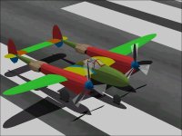
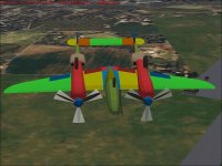
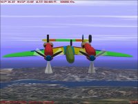
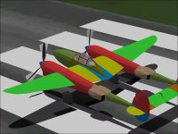
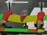
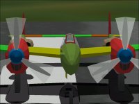
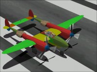
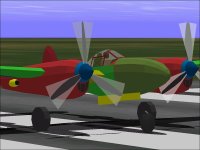
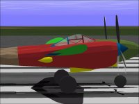
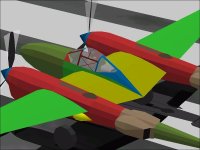
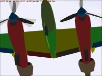
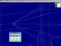
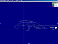
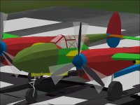
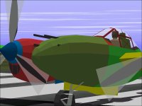
Lockheed P-38 Lightning - Design Study

AF99 Rebuilding

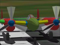
Combining the new Cowl into the project frees up two Components (which we are always short of) though it doesn't significantly change the parts count. (It actually removes two Glue Parts that are no longer necessary.)

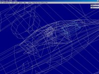
The major AF99 Rebuild is rearranging all of the Tail pieces from the "Tail" group to the "Tail, Left" and "Tail, Right" groups. This makes them line up with the Inner Wing group without bleeds. The bleed of the Radiator in a centrail Tail group through the Cowl in the Inner Wing or Boom section in either group looked to be very difficult to fix because so many pieces come together at that area.

An unfortunate result is that there is now a bleed of the Nacelle in the Body, Main group through the now missing central Tail group.
The fix here is rather easy but will expend one of the two Components saved from rebuilding the Cowl.

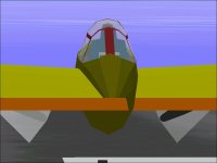
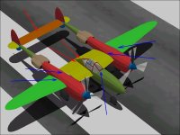
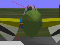
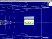
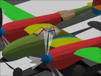
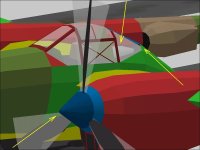
The current state is shown in the last screenshot along with arrows showing the current bleeds I know of. The Red arrows show the severe bleeds and the Blue arrows show the relatively minor bleeds. So far everything looks fixable perhaps even with the resources remaining.

Current Parts Count is now 1090 of 1200 allowed
Current Components Count is now only 25 of 30 allowed though 3 will be expended shortly to resolve the major bleeds noted above.

- Ivan.
 

Attachments

  • NewTailBleed.jpg
    NewTailBleed.jpg
    35.5 KB · Views: 0
  • CurrentBleeds.jpg
    CurrentBleeds.jpg
    59.3 KB · Views: 0
Makes me glad the only bleeds we have with CFS2 are weapons and props. Thankfully they are intermeten.
 
Bleeds

Hello Allen,

Bleeds are pretty much everywhere with add-ons for Combat Flight Simulator. I think everything has bleeds to one degree or another. This project will have a few, but hopefully they will not be bad enough to be seriously distracting. A lot of it is because Aircraft Factory 99 is the most common tool.

I figure a nicely shaped aeroplane is a matter of artistry. A bleed free aeroplane is more a matter figuring out how to use the tools to eliminate bleeds. When trying to rework an existing project, I prefer well shaped. As you can see by THIS project, the bleed issue can be reduced just by rearranging things a bit.

I also cheated a bit a couple months ago:
A while back, my friend Smilo was commenting that there wasn't a nicely shaped P-38 available that didn't have significant bleeds. I had found Eric Johnson's AFX quite some time ago and was pleasantly surprised that most of the dimensions were quite accurate. I decided to rework it for Smilo and along the way gathered enough information to build my own DP File and AIR File.

While doing the reworking of Eric Johnson's P-38J, I experimented with ideas in assembly and to see whether or not this project was feasible using my own build methods. The result was a "Maybe but with Great Difficulty". (Actually the answer was a "No", but that kind of answer is unacceptable.)

His aeroplane is mostly 8 sided sections while mine is mostly 12 sided. Mine is also a considerably more complicated design with more pieces.
I finished the rework of his project with a Parts count of around 770 and Component Count of 30 but the Cockpit remained empty.

I was hoping that my solution to the Coolant Radiators was enough to leave me some extra working room.

We shall see soon whether it was enough.

With a reasonable DP File and what I thought at the time was a pretty good AIR file, it seemed a shame not to try to build my own visual model for a complete aeroplane of my own.

- Ivan.
 
Last edited:
A Wing Fillet was added to each side to cure the Nacelle bleeds through the Inner Wings. The effect would have been the same but with 20 fewer Parts and 2 fewer Components if the Fuselage to Wing Template had worked.

Adding the Wing Fillet also added yet another bleed. It will cause a bit more difficulty when adding Flaps because the inner Flap sections begin at Wing Station 8 which is in the Fillet area and in a different Group than the rest of the inboard Flaps.

The one good result is that there is now a slight fairing between the Nacelle and Inner Wing at the front.

To cure the new bleed and address the other severe bleed from a rear view, The main section of the Horizontal Stabilizer was changed from Left-Right sections to Left-Center-Right sections. There is quite a lot of flexibility in choosing where to make the cuts: They just need to be outboard of the Wing Fillets and inboard of the Coolant Radiators.

The last screenshot shows the result.
The Parts Count is now 1122 of 1200.
The Components Count is now 28 of 30 with the 3 new Components at each Fillet and the Tail.

This project now has only 78 Parts remaining for quite a lot of missing pieces. I should have kept things a bit simpler or go back and see what can be done more economically.

- Ivan.
 

Attachments

  • RightTailBleedToFront.jpg
    RightTailBleedToFront.jpg
    38.1 KB · Views: 0
  • TailAdjust1.jpg
    TailAdjust1.jpg
    76.6 KB · Views: 0
  • Update1122Parts.jpg
    Update1122Parts.jpg
    57.3 KB · Views: 0
Flaps and Mass Balance

The P-38 Lightning was equipped with Fowler Flaps which greatly increased the Wing Area and could be used as "Combat Flaps" when partially extended.
When fully extended, they appear to just clear the trailing edge of the Wing with a noticeable gap between the Flaps and Wing.
Full Extension is 45 degrees.
Total Area is 42.60 Ft^2.

The Inboard section on each side starts at Wing Station 8 and extends to Wing Station 77.
The Outboard section on each side starts at Wing Station 118-3/4 and extends to Wing Station 180.

The Outboard Flap sections have a chord of 23.5 inches.
From doing some quick math, the Inboard sections also appear to have a 23.5 inch chord.

The Screenshots show 3 Flap sections per side because of the need to separate the Inboard section into a piece for the Body, Main group and one for the Inner Wing group.
The Body Main (Wing Fillet) pieces would disappear at certain angles and caused enough bleeds that I will be leaving them out until I can find a better solution.

Also added was a set of Elevator Mass Balance weights. They are not particularly complicated but cost another 8 of the increasingly scarce Parts.

I believe that in order to display and animate the Flaps properly, 6 Parts are required for each section that is built.
A Flap Well which is an "Insignia" Part facing Down.
A Upper Flap surface which is interior coloured (Probably Light Green for Zinc Chromate or perhaps Gray for Aluminum.
A Lower Flap surface which matches the bottom of the Wing and is textured the same as the Wing.
....and the 3 Glue Parts required to locate the actual Parts properly.

- Ivan.
 

Attachments

  • FlapsVersion1.jpg
    FlapsVersion1.jpg
    75.2 KB · Views: 0
  • FilletFlapsVanish.jpg
    FilletFlapsVanish.jpg
    74.1 KB · Views: 0
  • MassBalance.jpg
    MassBalance.jpg
    59.4 KB · Views: 0
  • P38 flap track.jpg
    P38 flap track.jpg
    90.7 KB · Views: 0
Wing to Cowl Bleeds

Bleeds betwen the Inboard / Outboard Wing sections and the Cowl Component were fairly simple though tedious to solve.
The basic idea was to extend each Wing Part until it slightly overlapped the Cowl.
(The Inner Wing Bleeds were actually changed a while back at the time the Wing Root Fillet Components were added.)

In the case of the Outer Wing, a slight change was made to the adjacent Cowl and Boom Parts.
(The Vertex was moved 0.20 Feet Up to line up with the extended Wing panel.)
I knew this change would be necessary at some point which is why I tried to create Left and Right side Cowl and Boom Components as "Opposite".
I was a bit surprised at how small the actual change was and how hard it is to see if you are not looking for it.

The end result cost no additional resources but with the previous changes we now have
1134 Parts
28 Components

- Ivan.
 

Attachments

  • OuterWingBleedFixed1.jpg
    OuterWingBleedFixed1.jpg
    51 KB · Views: 0
  • OuterWingBleedFixed2.jpg
    OuterWingBleedFixed2.jpg
    53.2 KB · Views: 0
Hi Ivan,

I am following this thread with great interest, as it addresses many problems I have found with wings, i.e. where they meet cowlings, nacelles, fuselage or booms, and provides interesting solutions!

Thank you very much indeed for your arduous work!

Aleatorylamp
 
Thanks Aleatorylamp,

Glad someone is getting something from this thread. I am getting the impression there is a much bigger audience than I had first expected. I had figured it would be the same crowd that hangs out at the "Conspicuous by Their Absence" thread.
As you can see, this is proving to be a bit more challenging than most projects.

- Ivan.
 
A Little Regression

I decided that the bleeds that were being covered by the Wing Fillets had too many other side effects and expended too many resources that could be used elsewhere and so they were removed.

The biggest problem with the Wing Fillets was that they made it very difficult to build the inboard Flap sections without bleeds.

The Cowl Intakes and Nose Gear Door were also added.
The Nose Gear Door on the Lightning is asymmetrical probably because there needs to be clearance for a fork on the Port side but not on the Starboard side. The longitudinal location of the Nose Gear Door is about 2-4 inches further aft according to sketches, but i moved them a bit to line up better with the lines in the model and also to give better clearance for the strut.

Accuracy can't be very good here because a 2D Part is being used to represent a very curved piece. The same will apply to the Main Gear Doors when they are built.

The Cowl Intakes on the Lightning have 3 openings.
The Center opening is for the Intercooler which exhausts at the bottom of the Cowl.
The two Outer openings are for the Oil Coolers which have their exhausts on the cheek of each Cowl.

Besides the two Wing Fillet Components that were removed, a new Component was added at the upper rear section of the Nacelle to cure a bleed problem there. It fixes most of the Canopy Frame bleeds but as can be seen in the screenshot, some of the side frames still vanish at certain angles. They can also be addressed if any Parts are left over.

All the Flap Parts are now in place. Note that this created a bleed of the upper surface of the Inboard Flap section through the nose.
If the Fuselage to Wing Template worked as expected, this would not be an issue at all.
Note also that this Flap bleed is not as bad as it looks because the Animation sequence can be adjusted to not display the Part when Flaps are fully retracted.

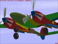
The overall screenshot shows the current status and quite a few missing pieces.

Parts Count is now 1153 of 1200
Component Count is now 27 of 30

- Ivan.
 

Attachments

  • CowlIntakes.jpg
    CowlIntakes.jpg
    58.7 KB · Views: 0
  • CFrameBleed.jpg
    CFrameBleed.jpg
    47.9 KB · Views: 0
  • FlapInboardBleed.jpg
    FlapInboardBleed.jpg
    47.6 KB · Views: 0
  • Update1153Parts.jpg
    Update1153Parts.jpg
    56.4 KB · Views: 0
Lightning's Intake and Turbocharger

They are two tear drop shaped curved scoops under the trailing edge of each outer wing.
These are the Intake Fairings for the superchargers on the Lightning.

Most models of the P-38 had two sets of superchargers:
The most obvious was the round / spiral shaped burned metal object on top of each Boom which was the Turbo Supercharger.
It was powered by engine exhaust which was piped from the outside of each cylinder head to a collector / plenum on top of the Boom just behind each engine. The plenum fed the Turbo.
This is also a recognition feature between Early and Late production versions of the Lightning.
The British contract Lightning Mk.I aircraft simply had no Turbocharger at all and were poor performers at medium to high altitudes.
The early model Lightnings had a noticeable gap between the exhaust plenum and Turbo because part of the ducting was hidden under sheet metal.
The later model Lightnings had all of the ducting exposed between where the collector and the Turbo.

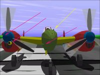
In constructing the Intake Fairings, I found that I had run out of Parts.
The 3 unused Components were expended for the aircraft's Wheels which were Structures.
Each Wheel as a Structure uses 30 Parts.
Each Wheel as a Component uses 12 Parts.

Each Intake Fairing is an 8 sided Structure in 3 sections and costed 25 Parts.
The intakes are located vertically on the Fuselage Reference Line and so I built them on the model's vertical centerline.
I was surprised when there was an overlap between each Outer Wing and he Intake Fiairing.
I went back and forth a few times to check dimensions until I realised that my model centerline is 0.42 Feet above the FRL.
When I made that adjustment things looked a LITTLE better but the Fairing still looked in the way to block the outer Flaps.
THEN I remembered that the P-38 has Fowler Flaps which move back as they extend. There isn't much clearanc but there is some.

Also worth noting is that AF99 seems to have an inconsistency in handling Structures:
The colour is as specified if neither the Forward or Aft Bulkhead option is selected. (Cockpit Dash area)
If either Forward, Aft, or Both Bulkheads are selected, the Structure uses the Group Colour but the ends are the colour selected for the piece.

Parts Count is 1173.
Components Count is 30.

There are still
Landing Gear,
Pitot Tube,
Guns,
and some other Minor details I still want to add.
It will be very close.

- Ivan.
 

Attachments

  • SuperchargerIntakeF.jpg
    SuperchargerIntakeF.jpg
    58.2 KB · Views: 0
  • SuperchargerIntakeS.jpg
    SuperchargerIntakeS.jpg
    50 KB · Views: 0
  • LightningJ_Turbos.jpg
    LightningJ_Turbos.jpg
    54.6 KB · Views: 0
  • SuperchargerIntakeB.jpg
    SuperchargerIntakeB.jpg
    43.1 KB · Views: 0
Hi Ivan!

This is getting really serious now. Nothing like pushing it to the limit.
Good luck on the end-spurt for the parts you need!

The colours for structures are usually annoying, especially if you want a black bulkhead for an intake or an exhaust, but you want the outside colour to be different from the group colour. I suppose AF99 is limited to 2 colours per item. Another thing I find annoying is the way a side texture flows around a bulkhead, and if I want it black, and I don´t want to use a separate insignia part as a "lid", a vertical line few pixels wide on one end of the texture helps, but it shows on the side too.

Anyway, Good luck!
Aleatorylamp
 
Cost Cutting Measures

I started on the Main Landing Gear and found a fairly elegant way to build the Gear Doors which unfortunately is a bit more resource intensive than what I had originally planned. I also realised that there are still so many pieces left to do that it is highly impossible to add all the remaining pieces with the remaining Parts.

With 30 Components used, there is no way to save a few Parts by replacing a Structure with a Component. Also, there are no more Structures that can be built much more economically with a Component.

Up to this point, all changes to the model to use fewer Parts has not degraded the appearance of the model except for removing the Wing Fillets.
Within the limitations of Aircraft Factory 99, there are always some compromises that are needed build an aeroplane project. My choices are usually to get the shape as close as I can and leave out some "non-essential" details. What I absolutely HATE is when it is necessary to remove or simplify pieces that have already been built.

With the Parts Count up to 1177 (after adding some Landing Gear pieces) it is necessary to free up resources to continue building.
The Radio will be replaced by one that is more compact (and hidden) which should save around 10 Parts.
The Spinner tips will be changed to remove the first row of polygons and will now end in a flat instead of a point.

The attached screenshots show the places that will be be affected along with a bleed that would need a couple more Parts to fix if there are any left over.

- Ivan.
 

Attachments

  • SpinnerSimplified1.jpg
    SpinnerSimplified1.jpg
    57.9 KB · Views: 0
  • RadioStructure.jpg
    RadioStructure.jpg
    138.3 KB · Views: 0
  • CostCuttingPain.jpg
    CostCuttingPain.jpg
    47.5 KB · Views: 0
Goofy Aspects of Structures

Hello Aleatorylamp,

The prior post shows the current state. Yeah, we are VERY tight at this point, but I knew that was happening when the Parts count broke 1000.

I very seldom leave an exterior strcture untextured unless it is a gun tube or fairing. I also don't generally leave anything set as the Group Colour which means I can change the Group Colour without affecting anything else such as when I added the Supercharger Intakes.
I do wonder what would happen if there are multiple untextured structures that all need to be different colours and all live in the same Group.

Regarding the need to texture the side of a Structure to give it a black opening, I have found that only two or three rows of black (very dark Gray because we NEVER use BLACK) pixels is sufficient. One row is used to set the actual colour and the other row is so that the colour doesn't change when the viewing angle is changed.

Keep in mind that although we can't fine tune the image on the texture file because each pixel is so large, we can locate those big pieces of coloured felt quite precisely on the aeroplane. Each pixel may be 2-3 inches square, but we can move it around by 0.01 ft or just over 1/10 of an inch. I was planning on covering this when I got to the appropriate stage of the Texturing Tutorial.

- Ivan.
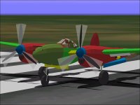
 
Main Landing Gear

The Front Spinner Structures have been reduced by one section.

The Main Landing Gear is complete at this point.
Each Main Gear is 15 Pieces (8 actual pieces and 7 Glue Parts to make things look right):
Inner Wing Group:
---------------------
Inner Door Upper
Inner Door Lower
Outer Door Upper
Outer Door Lower
Strut Top - This is an Insignia Part only outward facing because the inside is behind the Inner Doors.
Strut Middle - This is in the foreground when view is below the Gear Doors.

Left Gear Group:
-------------------
Main Wheel
Strut Bottom

Recall that the Engine and Boom centerlines are 96 inches from the aircraft centerline. (Wing Station 96)
The Main Wheel centerlines are 99 inches from the aircraft centerline.
The Main Gear Struts are 89 inches from the aircraft centerline.

With the theft of Parts from the Spinners and addition of Parts for the Main Gear:
Parts Count is now 1177 of 1200.

Note that there is a slight bleed of the Outer Wing through the Supercharger Intake.
This will not be adjusted until I can see the interaction with the deployed Flaps.

- Ivan.
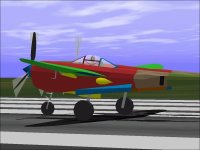
 

Attachments

  • MainGearComplete.jpg
    MainGearComplete.jpg
    50.8 KB · Views: 1
  • IntakeWingBleed.jpg
    IntakeWingBleed.jpg
    50.9 KB · Views: 0
Nose Gear and Pitot Tube

The Pitot Tube was relatively easy and only used 4 Parts as expected.
The Glue for it is particularly interesting because it isn't flush with the bottom of the Wing.
It is at a slight angle which creates a bleed when seen below the Wing's Trailing Edge from aft.
This angle is here to avoid a bleed when the Outboard Flap section is deployed.
My choice is usually to leave in small bleeds to avoid a huge bleed if a choice must be made. I believe the small bleeds are a bit less distracting.

The Nose Gear is also complete. My representation of the shimmy dampers is to just put in a part to acknowledge their presence which is better treatment than the Main Gear received. I don't think folks care much if the Main Gear is missing its torque links but if they are missing from the Nose Gear, it would stand out.

Parts Count is now 1184 and some choices need to be made:
The Guns will certainly be only 2D pieces for lack of resources.
I had intended to put in Dive Recovery Flaps even though the early J model didn't have them. They would be enabled by changing the AIR File and by adding an outline in the texture of the underside of the outboard wing.
I also wanted to have the scoops at the side of the Cowl. (Were these for Spark Plug cooling??)

The Guns can be added by Gluing to the Nacelle in the Main Body Group but that would require 10 Parts for the 5 Guns and the Glue for each Gun. Alternatively, they can be added to the Nose Group but would then would need to be Insignia Parts to avoid bleeds. As Insignia Parts, the far side Guns would always disappear.

A few Parts can be recovered by converting the Supercharger Intake to be 6 sided sections instead of 8 sided, but I don't want to do that.

- Ivan.
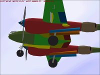
 

Attachments

  • PitotTube.jpg
    PitotTube.jpg
    57.7 KB · Views: 0
  • GluePitot.jpg
    GluePitot.jpg
    32.2 KB · Views: 0
  • NoseGearComplete.jpg
    NoseGearComplete.jpg
    60.3 KB · Views: 0
Decisions

Hi Ivan,

It´s certainly looking great!

With such a high parts count it always comes to decisions, and I´d definitely agree with omitting some small or less important details in favour of keeping the quality of more noticeable shapes or those that are more integrated into the aircraft!

It´s actually quite exciting to see how the job is progressing!

Cheers,
Aleatorylamp
 
Running out of Parts

Hello Aleatorylamp,

This is about as serious as I have gotten with running out of Parts. Surprisingly, AF99 hasn't had problems yet.
Other times, it has been running out of Components or having display problems which require simplification to some unpredictable degree.

It isn't just a matter of leaving out small pieces; It is more a matter of what we consider essential in a design. I have always thought the Supercharger Intake was a rather strange looking feature on the P-38, so this model had to have them.

- Ivan.
 
Lightning Gun Armament

The P-38 Lightning was typically armed with:
A 20 mm Cannon with 150 rounds.
Four .50 Cal machine guns with 500 rounds per gun.

From drawings, it appears that the 20 mm Cannon is aligned vertically with the Engines' Thrust Lines which puts them on the vertical center of this model. As expected, it is on the lateral center line.

From a Gun Harmonisation Chart the offsets of the machine gun bores are as follows:
The Upper MGs are 6.5 inches above the Cannon bore and 4.25 inches Left and Right of center.
The Lower MGs are 2.375 inches above the Cannon bore and 9.75 inches Left and Right of center.

The Cannon Muzzle is even with the Tip of the Nacelle. The MG muzzles are staggered to offset their magazine boxes in the nose of the aircraft.

Also from the Gun Harmonisation Chart, the ballistics of the Machine Guns and Cannon are all nearly identical.

Although the location of the guns makes for concentrated firepower to all practical ranges, it has another less optimal effect.
The guns and ammunition are quite heavy and located far forward of the aircraft's Center of Gravity and firing off the several hundred pounds of ammunition causes a large longitudinal shift of the CoG.

2000 rounds of .50 Caliber ammunition weighs 622 pounds.
150 rounds of 20 mm ammunition weighs 92 pounds.

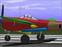
The first screenshot shows the appearance of the Guns from the side. I believe the two lower MG muzzles need to be extended further forward. Although the Cannon can be placed in the Nose Group, the other Guns need to be Glued to the front of the Nacelle, so the total cost is 9 Parts.

The second screenshot shows the less than optimal appearance of 2 dimensional "Guns" and also show the rather poor way AF99 handles Group Glue between the OUTER Wing and Fuselage: The viewing plane happens to be on the aircraft centerline.

- Ivan.
 

Attachments

  • NoseGuns.jpg
    NoseGuns.jpg
    53.6 KB · Views: 0
  • GroupGlueProblems.jpg
    GroupGlueProblems.jpg
    60 KB · Views: 0
Getting there!

Hi Ivan,

It´s a real achievement to be able to get everything one wants in when the 150% limit keeps coming up. With luck some things can be done with fewer parts, and one can scrounge parts for what´s still needed!

Thanks to several items in this design study I had a series of surprisingly successful gluing tasks on the "big plane" I´ve almost finished reworking. I´ve even managed to scrounge parts for the ventral machine gun by dividing a complicated engine+radiator structure into two, sequentially gluing some of it which was causing bleeds, and grouping the radiator with the propellers and spinners. There I used a convenient gluing sequence, so there´s no bleeds at all! Amazing... The same with the 3 crew members (albeit very simple shapes), their wells and the walls on either side - nothing bleeds!!

Thanks again for all this lot!!
Cheers,
Aleatorylamp
 
Dive Recovery Flaps

Although the early P-38J did not have Dive Recovery Flaps, They were standard on later models of the Lightning.
The P-38 had a very low limit on its maximum diving speed.
The limit was not because of structural limitations but because of control limitations.
At around 0.65 Mach, the Lightning would enter "Compressibility" and the wing would lose lift AND the elevator would lose effectiveness.
This phenomenon was known as "Nose Tuck".
At this point on early Lightnings, the only option was to adjust elevator trim to attempt to pull out. Hopefully the recovery would happen before impact with the ground.

With the late J model Lightning, "Dive Recovery Flaps" were installed on the underside of each outboard wing panel.
When deployed, they would cause the nose of the aircraft to come up and to a lesser extent also act as air brakes.

Although my model is not intended to have Dive Recovery Flaps, I thought it would be interesting to add them to the model and prevent their use through the AIR file. For a later model Lightning, all that would be necessary would be to slightly change the texture of the underside of the wing and enable the "Spoiler" in the AIR file.
Strangely enough, Enabling the Spoiler is done by changing the Spoiler Angle in Record 320 to a non-Zero value. The "Spoilers Available" variable seems to have no effect. The deployed Dive Recovery Flap appears to be at an angle of 45 degrees so that is what I used even though the number here can be anything.

Temporarily, I changed my own AIR file to test the effect. It should look much better when textured and animated. It will also not affect my version of the Lightning because the pieces will not display when the Spoiler is not deployed.

The forward section of the Dive Recovery Flap has a chord of 8.5 inches. The Brace behind it has a chord of 7 inches.
Their location is from Wing Station 122 to Wing Station 180.

As can also be seen, I found it necessary to simplify the Supercharger Intakes to a Hexagon Structure to free up some resources.
The Panel area of the Cockpit has also been extensively modified but is not shown here because I have already gone through about 4 designs and am still not sure what it should look like.

- Ivan.
 

Attachments

  • EconomyIntakes.jpg
    EconomyIntakes.jpg
    51.7 KB · Views: 0
  • DiveFlapLF.jpg
    DiveFlapLF.jpg
    58.5 KB · Views: 0
  • DiveFlapLA.jpg
    DiveFlapLA.jpg
    57.3 KB · Views: 0
  • DiveFlapBelow.jpg
    DiveFlapBelow.jpg
    43.1 KB · Views: 0
Back
Top