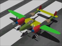
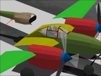
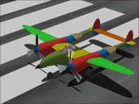
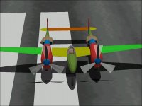
Lockheed P-38 Lightning - Design Study

AF99 - Fuselage to Wing Templates

Strictly speaking, this post is not really about a design study of the P-38J Lightning.
It is about the tool that I am using to build the 3D Model and its limitations.

Aircraft Factory 99 has a feature that is described as a Fuselage to Wing Template.
It defines a viewing plane that is not orthogonal to the axes that will be the separation between the Fuselage and say the Left Wing.
On the P-38, the join between the Nacelle and the Inner Wing section between the Nacelle and Engine is a very odd line. From a plan view, the line begins at the Wing Root at the Leading Edge (about 1.6 Feet from the aircraft centerline) and ends at the tip of the Nacelle ON the aircraft centerline.

This is a natural place to use a Fuselage-Wing Template.

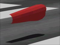
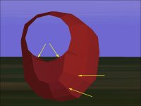
What I found is that the template does not work with the project as built thus far. Neither side works and the behaviour is somewhat odd.
As a quick test, I used only the Inner Wing sections and the Nacelle along with the templates and they worked exactly as expected.

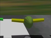
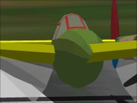
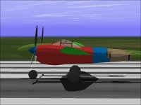
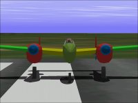
The attached screenshots show the Bleed versus No Bleed from nearly the same angle.

....
 

Attachments

  • FuselageWingTemplate_NoBleed.jpg
    FuselageWingTemplate_NoBleed.jpg
    26 KB · Views: 0
  • FuselageWingTemplate_Bleed.jpg
    FuselageWingTemplate_Bleed.jpg
    33.5 KB · Views: 0
AF99 - Fuselage to Wing Templates

So....
Somewhere between a minimal Three Components and the current project assembly there is an object that is causing the template feature to fail.

I have gotten to the point where I can add or remove an object and the template feature works or fails. Now the trick is to figure out what are the actual limitations on the use of a Fuselage to Wing Template.

The attached screenshots show the assembly state at which the bleed starts.
If the WHEELS are removed, the Fuselage to Wing templates start working again and the bleed disappears.

The next step is to figure out what may be causing it and whether I can work around it.
Here is what I know thus far:

1. It is not a simple resource count limitation. This project is up to 900+ Parts versus a "Maximum" of 800 Parts, but my experiments with Eric Johnson's AFX for the P-38J also had the same bleed problem and the Parts count was only about 765 or so.

2. It is a combination of factors. Removing just the wheels from the full assembly does nothing to make the template work.

3. I suspected that it was an "Opposite" side assembly option similar to the earlier one with "Add Left-Right Pair", but duplicating the wheel structure on the Right side made no difference.

4. The Fuselage-Wing Template feature is having what appears to be the opposite effect from that intended. The bleed of the Inner Wing section appears to be worse with the template than without.

Time for more experiments.
- Ivan.
 

Attachments

  • FuselageWingTemplate_FirstBleed.jpg
    FuselageWingTemplate_FirstBleed.jpg
    48.8 KB · Views: 0
  • FuselageWingTemplate_FirstBleed2.jpg
    FuselageWingTemplate_FirstBleed2.jpg
    50.4 KB · Views: 0
Aircraft Factory 99 Templates

I had hoped to use the Fuselage to Wing Templates as a way to save 2 or 3 Components and 20 or so extra Parts.
From what I can tell with a few more test assembly sequences, it appears that the Template location is being mirrored Left to Right along with another transformation that I have yet to isolate. I have a few guesses, but not enough to do more than rambling with a post.
This seems like a job for a custom visual model that can show the template's effect better than the curves on the P-38 do.

For now, I will just presume that I will need to spend 2 extra Components to kill the Wing Root bleeds or just accept that the bleed is there.
Next step is to re-arrange the Nacelle pieces as they would need to include a Pilot figure.

- Ivan.
 
I've seen that bug in DPED and in Model Converter X with old models. For going from a F to J I only had to make new engine cowl.

View attachment 16553

I made clone of the engine and extrueded from the point where blue and peach meet. I extrueded it forward (Right) to the first point than again to the end and put the angle and capped it. With that done I deleted the rest of the engine parts around the new extrued engine cowl and changed it color to blue. With the extruing done I did the shaping and adjusted the texture mapping.

View attachment 16554

This is what the new extrued engine cowl looks like by it self. I part linked it to the unedited F model engine. It added about 50 polygons to per engine cowl.
 
Wing-fuselage templates: Are they really triangles?

Hi Ivan...

On the 2 or 3 four-engined planes I have built so far and the 1 or 2 that I´ve upgraded from FS5 for FS98, I always tried to use the wing/fuselage triangular template and it has never worked for me. For that matter, the Nose/wing template has never worked either. The templates only made things worse.

When I started reading about the templates here in your thread, I went to the AF99 Help files and read the useless explanation: "actually a triangular Wing/Fuselage Template" can help if the wing intesects the fuselage at an extreme angle (dihedral?), and "actually a triangular Nose/Wing Template" can help if the wing is tapered and has multiple portrusions. This is followed in both cases by a very unclear diagramme.

Now really!! So I then inspected the T6 Texan, one of the default AF99 example planes that the "explanation" refers to, and saw that the templates looked like only lines not triangles - they were indeed specified as lines and not solids!! OUCH!

So I looked at the stupid diagrammes again, but this time really squinting.
YES SIR! They ARE lines, not triangles.
The "triangular template" is just a HOOKED LINE!

So much for that! It really made me feel stupid. ...and angry too! No wonder they didn´t work. It´s too late at night now to go back and try out all the hooked lines on the 6 four-engined models of the past... I might have saved myself a lot of bother. How not to write a user´s manual!

Well anyway, you probably know that already and are already using hooked lines and not triangles!

Your tutorial is very interesting ideed, by the way.
Cheers for now!
Stephan
 
P-38F to J Radiators

Hello Allen,

You might also want to build new Coolant Radiators for your J Lightning.
I was trying to hint at that in my earlier response but could not see enough detail to confirm that it was still a F Radiator.
The F model had a much flatter Radiator with a much taller but narrower opening.
I believe the Radiator switched to the new shape with the H model but the Intercoolers didn't change until the J model.

The best example of a F Lightning is "Glacier Girl". I believe the contours are faithful though you never know with a complete new build which is really what that bird is.

The Red Bull Lightning (formerly White Lightning of Lefty Gardner) is kind of a weird mixture: It has the L model Radiator because it started off life as a L, but it has the earlier model Cowl without Intercoolers. Then again, it doesn't have Turbos any more so I suppose Intercoolers aren't really necessary.
An interesting thing is that the equipment failure that ended the last flight of "White Lightning" was a supercharger impeller explosion, so I guess even the regular mechanical supercharger is dangerous and not just the turbocharger.

Regards.
- Ivan.
 
Wing to Fuselage Templates

Hello Aleatorylamp,

I thought about the Line versus Solid issue when I first encountered the problem. I changed one side to be a Line while leaving the other as a Solid. It made no difference. When one worked, so did the other. When one failed, so did the other.

They obviously DID work at one point as my testing with only three Components showed. They even with with a lot more.... Up to the point where I added the Wheels.

They HAVE worked for me in the past sometimes and on other projects they did not. I never quite understood why and still do not. I believe that at a certain resource limit, they transform somehow and when I have no other projects in the works, I will go experiment a bit more. The transformation is mostly a mirror because the Right works better as a Left and vice versa, but it isn't an exact mirror because leaving them out entirely works (doesn't work?) even better.
Until I can reliably predict the effect, I won't use it on a project.

The Nose to Wing Templates actually DO work sometimes. I know because I have used them. That was the easiest way I found to prevent the Cowl and Nose on the Macchi C.205 Veltro from bleeding through the Wing Cannon. I don't use them often so I don't know if they fail sometimes.

There are actually a bunch more bugs that I have encountered in AF99 over the years, but I had not bothered to document them for later reference. It was enough just to find a workable solution around the problem.

I don't know if I would really call this thread a Tutorial. I am not really trying to teach anything. I am not showing how I do things. I only describe a little and show the result.
I figured "Design Study" was a better description because it is really about the shapes of the late model P-38 and my attempts at trying to represent them within the limitations of Aircraft Factory 99. Also, I don't know which will come first: Finishing the model or hitting a resource limitation. I know it will be VERY close either way.

I really wish I had the source to Aircraft Factory 99. I can see many ways to make it a much more powerful tool than it is now.

Regards.
- Ivan.
 
Templates

Hi Ivan,

Yes, Design Study rather than tutorial, or even AF99 testing bed!

OK, thanks - so lines make no difference, and the templates do work on simple models.
Too bad... Who wants simple models?

It´s clear that after a certain degree of complication, AF99 starts glitching. This "threshhold" varies - sometimes it happens when too many individual parts are being used and AF99 protests, asking for "more conventional building techniques", i.e. wanting more components and/or structures to simplify its own life... Oh? Then why does a simple box-structure use a higher % parts count than 6 individual parts for the same shape? There aren´t even any bulkheads! Another AF99 mystery.

Textures start messing up too, and I have had to write coordinates manually into the .afa building files - so it isn´t always the WinXP Spanish keyboard config that is the culprit, as I recently thought. The decimal point just disappears and is substituted by a decimal comma, ruining the texture spread.

Although I can´t programme any source code, I did contact Abacus once by e-mail AF99 quoting my user and access code to ask about this. They were very kind and attentive, and surprised that anyone still used AF99, but said nobody there knows anything about it anymore because the programmer, who was there at the time the author wrote AF99, had left.

So it looks like workable solutions around the bugs are our only resort. Maybe it just adds to the fun!

Cheers,
Stephan
 
Hello Aleatorylamp,

I know the Nose to Wing Template worked for the Macchi Veltro and that is hardly a simple model.
It even held together after texturing which occasionally causes problems when the project is near its limit.

From what I can tell, there are some internal limits to Aircraft Factory 99 that are not obvious.
The absolute HARD limits of 30 Components and 1200 Parts is pretty obvious.
The "Suggestion" for 75 Parts (or whatever it is) for a Component is not a hard limit.
I have exceeded it without consequence as for the Blohm & Voss BV-141B.
I have Component failures but I believe the reason was different.

If you look at the SCASM source for one of the models, with a Component, each of the Vertices is listed first with their offsets and then the polygons refer to those Vertices.
The interesting thing is that the ordering of the vertices determines the facing of the Part (as you would expect) even though the ordering of the vertices is entirely irrelevant inside AF99.
Although two Components may have the same number of polygons, I believe if many of the vertices are shared, it uses fewer resources inside AF99. My belief is that the limit is more about the number of vertices in the Component than the actual Parts count.

Occasionally, there is a build failure even though the resource useage is still well off the limit.
You can see this with the FW 190A screenshots shown earlier.
I have hit the same problem when extending the wings on the A6M2 Reisen.

I hit a similar problem with the B-25C Mitchell at about 1180 Parts:
I originally built the Tail Skid as a Structure. I believe a Structure normally costs about two more Parts than the simple count of its faces would suggest.
The problem was that other polygons started disappearing as I added pieces. I cured the problem by changing the Tail Skid to a Component which slightly lowered the Parts count. As you know, Components are scarce which is why I try not to use them unless I have no choice.

From a programming standpoint, perhaps it is an Array that is dimensioned a bit small. Perhaps it is a matter something called Heap size that limits the amount of memory that can be allocated.


Hello Allen,

I looked over some photographs last night. Seems like the H Lightning had the newer engine of the J model but still had the older style Coolant Radiators.

- Ivan.
 
A Lightning Pilot

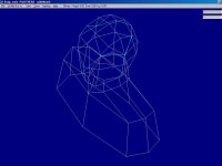
My assembly techique for most AF99 projects starts at the Cockpit with a Pilot figure.
This is because the Cockpit has the most small pieces that all come together in nearly the same place.

With AF99, the concept of a "Viewing Plane" is implemented with a "Glue" Part to attach a new piece to an existing assembly.
Each Glue Part describes an infinitely wide geometric plane that is used to determine what is in the Foreground and what is in the Background for display priority. Incorrectly determining display priority (Foreground / Background) is the cause of bleeds that are so common in CFS aeroplanes.

I have used the same pilot figure for the last several years.
In general, all that is needed to place him in a new aeroplane is to move all the Parts Longitudinally and Vertically and then extend or shorten the lower edges of the shoulder Parts to match the new Cockpit Floor.
Because most Pilots for my projects are at the aircraft centerline, there is no need for a Lateral shift.
To do this, I use a program called CMoveIt (Component Move It) which takes a set of offsets and relocates all the Parts within a Component.

The first screenshot shows the two Components required for this figure. Together, they cost two Components and about 65 Parts.

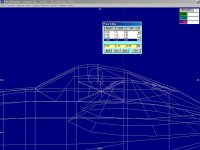
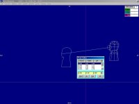
To locate the Pilot, I creaed a template from the Pilot's Components and use that to judge the correct location as can be seen in the second screenshot.

From photographs, the Pilot appears to sit with his head very close to the top of the Canopy with his eyes just above the window section that can be lowered. The longitudinal location is very near the peak of the Canopy.
My location by eyeball needs to be confirmed by a look at the pilot's seat location within the cockpit.

The Pilot in the P-38 sits very high in the cockpit. The edge comes down nearly to his waist.
In this case, this caused a little concern because if the lower edge of the Pilot extended too far, it would no longer fit onto the texture file allocated for it.
The Top and Bottom limits for the Pilot Shoulder texture are 1.40 feet apart.
The Cockpit edge is 0.95 above the Aircraft CoG.
As can be seen from the screenshot, the highest part of the Pilot's Neck is 2.08 feet above the Aircraft CoG, so we are still within the limits for using the current texture.

- Ivan.
 

Attachments

  • PilotFigure.jpg
    PilotFigure.jpg
    43.6 KB · Views: 0
  • PilotLocation.jpg
    PilotLocation.jpg
    69 KB · Views: 0
Can I just widen the F radiator? Making new ones would be quite a pain. Geting the new radiator texture to match the stock would just a pain....
 
Hello Ivan,

I´m so sorry! By no means did I want to imply that your Macchi Veltro is a simple model!
I meant the T6 Texan default AF99 aircraft which the AF99 help files refers to, implying only that my 4-engined models and the P38 in this thread were too complicated for effective use of these templates.

Your insight and conclusions as to the possible cause are certainly very interesting and illustrating, and your examples of how to work around them will help more than one builder!

Thanks!
Stephan
 
Radiator Shapes

Can I just widen the F radiator? Making new ones would be quite a pain. Geting the new radiator texture to match the stock would just a pain....

You be the judge. Most people won't know the difference.
Consider that CFS has been around for well over a decade and I don't believe there has ever been a good flight model for the P-38 Lightning. At least I have never found one.

The stock aeroplanes in all the Combat Flight Simulators up to Version 3 all have some shape problems somewhere. I am sure the radiator won't be the biggest issue of that aeroplane. I was just pointing it out because this thread was intended as an exploration of the features and shapes in the P-38J. I will also build an early model Radiator assembly at some point in this thread, so folks can do a comparison then if they haven't already done it with photographs from the Internet.

THIS Lightning will have some shape problems as well, but they are due mostly to the resource limitations of the tools and my build methods which are hardly economical.

- Ivan.
 
Cockpit Pieces

Shifting the Pilot to match the profile was very easy.
Finding the offsets was just a matter of matching up identical points.

A few more Cockpit pieces had to be built.
The Radio is a simle rectangular Structure.
The Walls and Floors are simple Insignia Parts matched to the edges of the Nacelle.
The very prominent Armour Plate behind the Pilot was an eyeball approximation of an image from a technical drawing.
It is actually two Parts to avoid any concave edges. I have absolutely no concern for these two pieces bleeding through each other because they are supposed to be co-planar polygons.
The Canopy Frame had to be split into a Left and Right Component with some overlap at the top to avoid bleeds.

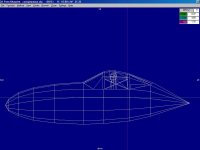
The last two screenshots show the current status with a close up of the Canopy area.
This area is now full of bleeds and I am starting to run short of resources to address those bleeds.
Note that there are still very large missing areas that MUST be completed for any reasonable model.

Resource Count is now 25 Components out of 30 allowed and 1003 Parts of 1200 allowed.

The missing areas have been saved for last because of my "Least Commitment" principle of building:

The Control Panel and front of the Cockpit could be built as a Component (easiest), a Structure (not as nice looking) or as a set of parts glued together which would look like a "Sharp" Component but is most likely to cause a AF99 Failure. The choice depends on what resources remained after building more essential things.

There are still 2 Structures required for the Supercharger Intakes below the trailing edge of each outer wing section. I have never seen any other CFS Lightnings with those pieces as anything other than textures, so if I left them off, folks probably would not notice.

There should be an additional Component added to each Wing Root to remove some of the bleeds betwen the Inner Wing and Fuselage. From close up, these bleeds are much more severe with the new Cockpit pieces added.

There should be an additional Component added to each Boom in the missing section in order to get the shapes right with few bleeds.

Another Aircraft Factory 99 "Bug" can be seen in the last two screenshots:
The "Body, Main" group colour is Light Gray.
The Radio is a Medium Blue Structure with "Both Bulkheads" selected.
From the screenshots, it appears that the Radio is Light Gray with only the Bulkheads as a darker colour.
This "Feature" can be used to advantage with Gun Barrels to make the Muzzle Back (Structure colour) while the tube is coloured a lighter shade to be determined by the group colour.

- Ivan.
 

Attachments

  • PilotShift.jpg
    PilotShift.jpg
    28.8 KB · Views: 0
  • CockpitPieces.jpg
    CockpitPieces.jpg
    41.7 KB · Views: 0
  • Update121201.jpg
    Update121201.jpg
    54.1 KB · Views: 0
  • CockpitInSimulator.jpg
    CockpitInSimulator.jpg
    36.9 KB · Views: 0
Radiator Openings

I was debating on whether or not this was even worth its own post.

Radiator Openings were added.
They turned out pretty much as expected with 6 actual Parts and 6 Glue Parts to locate them.

So now the count is 1015 Parts.

Behind the scenes, quite a lot was changed, but nothing that would result in any change in appearance other than some minor colour changes so that like-coloured pieces are not visually adjacent to each other and so that pieces do not have to be added as "Opposite" in AF99.

This is done rather easily with a program called CMirror (Component Mirror).

- Ivan.
 

Attachments

  • RadiatorExhausts.jpg
    RadiatorExhausts.jpg
    50.2 KB · Views: 0
  • RadiatorInlets.jpg
    RadiatorInlets.jpg
    50.9 KB · Views: 0
You be the judge. Most people won't know the difference.
Consider that CFS has been around for well over a decade and I don't believe there has ever been a good flight model for the P-38 Lightning. At least I have never found one.

The stock aeroplanes in all the Combat Flight Simulators up to Version 3 all have some shape problems somewhere. I am sure the radiator won't be the biggest issue of that aeroplane. I was just pointing it out because this thread was intended as an exploration of the features and shapes in the P-38J. I will also build an early model Radiator assembly at some point in this thread, so folks can do a comparison then if they haven't already done it with photographs from the Internet.

THIS Lightning will have some shape problems as well, but they are due mostly to the resource limitations of the tools and my build methods which are hardly economical.

- Ivan.

I'm not doing any major change to the shape. Just some Q and D engine intakes and un-mirroring the aircraft textures. I did pull out the rads intakes some.

View attachment 16645
 
I'm not doing any major change to the shape. Just some Q and D engine intakes and un-mirroring the aircraft textures. I did pull out the rads intakes some.

Looks like a pretty good solution tp me. M$ also mirrored the textures on CFS2? That is pretty silly.
I should start up my copy of CFS2 to see what the rest of the stock Lightning looks like. I have been a bit hesitant because I only have a 15 inch monitor on that machine right now. A monitor failed on another machine and mine had to give up its monitor.

CFS2 at least has directional propeller rotation which is needed on the Lightning but generally not represented on CFS1 versions.
THAT was a fun exercise with this project.

- Ivan.
 
The remaining sections of the two Booms were added.

Parts Count is up to 1073 of 1200 allowed.
Components Count is 27 of 30 allowed.

This is getting too close to the limit because there are many pieces that still have not been created.
There are still no Landing Gear Struts or Doors.
The Flaps still need to be added.
I still want to add Supercharger Intakes.
The front of the Cockpit is still missing.

There are a few bleeds that require duplication of a piece or two and will expend more Parts.

The last three screenshots show a few of the bleeds that become obvious when more pieces are completed.
None of the bleeds is particularly difficult to remove IF there are enough remaining resources.
Since there are not many resources left, it will be a serious bit of juggling and compromises and probably some non-intuitive reconstructions.

- Ivan.
 

Attachments

  • BoomPiecesAdded.jpg
    BoomPiecesAdded.jpg
    56.8 KB · Views: 0
  • WingBleeds.jpg
    WingBleeds.jpg
    43.8 KB · Views: 0
  • RadiatorBleed.jpg
    RadiatorBleed.jpg
    47.7 KB · Views: 0
  • OuterWingBleed.jpg
    OuterWingBleed.jpg
    43.5 KB · Views: 0
Looks like a pretty good solution tp me. M$ also mirrored the textures on CFS2? That is pretty silly.
I should start up my copy of CFS2 to see what the rest of the stock Lightning looks like. I have been a bit hesitant because I only have a 15 inch monitor on that machine right now. A monitor failed on another machine and mine had to give up its monitor.

CFS2 at least has directional propeller rotation which is needed on the Lightning but generally not represented on CFS1 versions.
THAT was a fun exercise with this project.

- Ivan.

Yup. All aircraft in CFS2 had mirrored textures. TheB24Guy did Overhuals of all of them but the F4U (D-Bolt had already did one or two) to un-mirrored them, basic VC and working gauges added to the AI models a long time ago.

I still use a 15 inch monitor (Gateway FPD 1530 that matches the Gateway 500x it is attached to. :adoration:)
 
AF99 Rebuilding

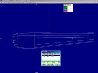
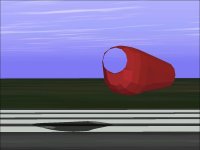
Here was the attempt to connect the new Boom section to the existing Cowl Component.
I had been reluctant to do this because it would make the Cowl Component very long and harder to texture well.

Only one texture file (256 pixels wide) must be used to cover 16.52 feet (more likely oto be 16.64 feet) on the model which makes each pixel cover a 0.78 inch square. Such big pixels make it difficult to put in good detail on a paint scheme.
The Lightning is a very large aeroplane and this is one of the consequences of building a large aeroplane in Combat Flight Simulator.

This single Component now contails 88 Parts.
I had been reluctant to add the new Boom pieces to the Cowl Component because I know that although it will not necessarily cause a bleed in the Component, it will make the Turbocharger bleed through the upper rear side. Luckily, most of the bleed will be covered by the Radiators behind them.

Note also the contour corrections as compared to the Cowl image posted earlier.
 

Attachments

  • LargeComponent.jpg
    LargeComponent.jpg
    36.6 KB · Views: 0
  • LargeCowl.jpg
    LargeCowl.jpg
    39.9 KB · Views: 0
  • LargeCowlAft.jpg
    LargeCowlAft.jpg
    29.9 KB · Views: 0
  • CowlSecondTry1.jpg
    CowlSecondTry1.jpg
    29 KB · Views: 0
Back
Top