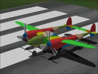
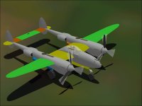
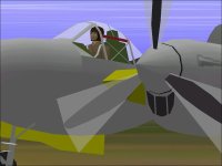
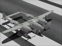
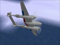
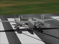
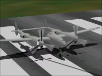
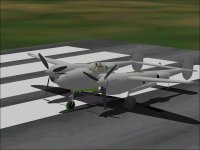
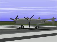
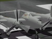
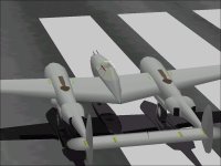
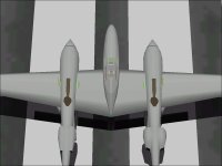
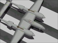
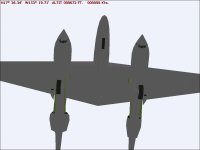
Lockheed P-38 Lightning - Design Study

Finished?

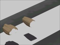
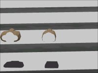
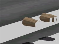
There are small scoops on either side of each cowl which I believe are for spark plug cooling.
They look quite prominent in the current "Sharp" Component but may be much less visible when the Component is made "Smooth" for painting.

After adding those, the Resource count is as follows:
1195 Parts of 1200 allowed.
197 Separate Parts in the Assembly out of 200 allowed.
30 Components of 30 allowed.
6 Structures of 30 allowed.

For all practical purposes, the model is as good as I know how to do within AF99 limitations at this point.
Many improvements can be done within SCASM, but the purpose here was to build at least the exterior model entirely within AF99 limits.

There is still quite a lot of experimentation that can be done with the Fuselage to Wing Templates which I intend to do.

Next step with this model is animation of the current assembly.
- Ivan.
 

Attachments

  • Update122801.jpg
    Update122801.jpg
    60 KB · Views: 0
Hi Ivan,
It´s certainly looking good. Congratulations!
Just a small query: I was wondering whether you were planning to put in wheel-wells that appear then the undercarriage is out, or is this perhaps not on your agenda because of the inexact animation which retards their appearance until the undercarriage is fully extended.
Cheers!
Aleatorylamp
 
Hello Aleatorylamp,

The Wheel Wells are not on my list but not because the animation would be inexact; It is simply because I have expended 197 of 200 individual Parts.
To put in Wheel Wells would require a minimum of 2 Parts per Wheel which along with the Glue Parts adds up to 12 more Parts which are simply not available in the AF99 Project.

Sequencing the Wheel Wells to match the animated Landing Gear is actually rather trivial. I believe I have done this on most of my other projects using SCASM.

For the purposes of this Design Study, my goal was to build and texture the entire exterior model using Aircraft Factory 99 and Aircraft Animator.
SCASM was to be used for tasks that AF99 us clearly incapable of accomplishing such as the Virtual Cockpit view, and very minor Animation Refinement.
I wanted a model that as loaded into the simulator would show at least from the exterior view what can be accomplished with AF99.
(It was one of those: "If others can do this, why can't I?" kind of things.)

Using SCASM, There are really no practical limits to the resources available and the Fuselage to Wing Templates would be trivial to do.
With only SCASM limitations, I would also be adding in a couple hundred more pieces over the next couple of months.
As it is, I am more or less satisfied with what is here as long as I can get the model textured without breaking anything.

- Ivan.
 
Hi Ivan,

I see. Depending on priorities, of course not everything is possible. For me, sometimes a simplification works by putting the wheel wells with insignia down, tagged as gear down but unanimaterd in AA, into the body and the lower engine nacelle groups - this way I save the glue to keep the gear separate from the doors. Of course, with some doors closing with extended gear, it becomes difficult, as the closed doors then have to cover the wheel wells - but that´s usually only on jets...

AF99 limitations, are very frustrating with complicated models. If it´s not parts numbers, it´s degree of complication. At the moment I´m battling with the Zeppelin Staaken R.6 and the Gotha G.4, trying to include guns and crew. It´s a nightmare with the transparent cabin and the hollow fuselage respectively, and looks like I´ll have to make those solid, and it´s taking much longer than I expected. We´ll see!

Anyhow, I´m looking forward to watching how the Lightning will be textured and animated. That will doubtlessly be very interesting!

Cheers,
Aleatorylamp.
 
Unusual Animations

The model of the Lightning that was uploaded was animated though not textured.
Many things can be done with Aircraft Animator though not necessarily in the way that one might expect.

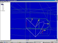
The Dive Recovery Flaos come in two sections per side. The Forward Section (the actual Flap) is animated pretty much as one might expect.
The Aft Section is also animated rather simply, but the axis of rotation has been shifted a bit.

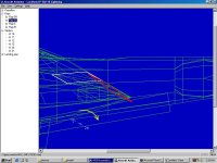
The Lightning had Fowler Flaps that extended back as well as down. When fully extended, the leading edge of the Flaps werenearly even with the trailing edge of the wing. This can also be done was a simple rotation though again the axis must be shifted s.

- Ivan.
 

Attachments

  • DiveBrakeSpoilerAnimation1.jpg
    DiveBrakeSpoilerAnimation1.jpg
    72.9 KB · Views: 0
  • DiveBrakeSpoilerAnimation2.jpg
    DiveBrakeSpoilerAnimation2.jpg
    98.8 KB · Views: 0
  • FlapAnimation.jpg
    FlapAnimation.jpg
    73.8 KB · Views: 0
Hi Ivan,
I find the whole concept of this design study extremely appealing, as it proves that complicated aircraft can indeed be produced decently with AF99 if one ably maneuvers within its limits. It also shows how an effective criteria of defining priorities prevents a lot of frustration.

I like your minimalistic, parts-saving use of 2D parts in certain areas - e.g. animated landing-gears struts - where 3D isn´t vital. (A fixed gear would be different, as it shows all the time).

Very nice, the Fowler flaps! AA does these really well if the axis is shifted correctly!

Re. dive-brake spoiler animation: Very interesting, how you manage the second rotating axis - I´m still trying to figure out how it works! I´ve never had much success using the "H" factor, and usually hide certain sequence-sections differently, but less effectively. This, however, seems to be one of the "secrets".

Cheers,
Aleatorylamp
 
Aircraft Animator Bugs

The Aircraft Animator screenshots from my prior post along with the model that has been uploaded contain sufficient information for anyone with access to the Aircraft Animator package to experiment with and alter the animation for my P-38J. The model that was uploaded earlier includes the animated parts files that AA uses to save previous animation sequences.

This brings up a rather annoying "Bug" in Aircraft Animator that I have encountered numerous times:
There are certain animations that the package will add to the model but will not save to be used again.

The diameter of the Transparent Propeller Disk may be adjusted to 0.01 Meter in the MDL, but is only recorded to 0.1 Meter.
The P-38J has a propeller diameter of 11 feet 6 inches and I found 1.78 Meters to work well but it is only recorded as 1.8 Meters.

Aircraft Animator will record Flap animation sequences faithfully if the MDL file contains "Flap Retracted" pieces (as my Lightning model does) but will not record sequences if all of the Flap pieces are tagged as "Flaps Extended".

Aircraft Animator will also not record Spoiler animation sequences if the MDL only contains "Spoilers Extended" pieces as my model does.
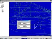
Although AA does an excellent job of guessing axes of rotation, the odd animation sequence of the "Spoiler Brace" must be recorded elsewhere (such as the attached screenshot) and entered each time by hand.

There are other bugs as well in the "Motion Ranges" section which I have encountered in other projects but not on the Lightning.

- Ivan.
 
Hello Aleatorylamp,

I am glad there is some interest in this "Design Study". The Design Study aspect is why I am including so many of the specifications and other technical details on the P-38 as I go. Unfortunately, I was doing the building and posting the progress as I went, so it is not planned out ahead of time and the data and even the discussion may not be as organized as one might want.

I wonder if others are finding amusement in watching the development of a fairly complicated project which was pretty sure to run out of resources at some point and seeing the backtracking and rebuilds needed to stay under some ridiculously low resource limits. A couple weeks back, I would normally have taken a break and switched to a different project if I wasn't posting progress on this thread.

Regarding 2D pieces:
My preference would be to have done things with 3D Components in most places such as the Landing Gear Struts but there was really no option to do this with other design choices I had made. I wanted the Struts to be as near to the actual location as I could manage but from certain angles, the 2D Part leaves an obvious gap.

I believe in most cases that a 12 sided cross section is optimal with projects in AF99 as a compromise between a reasonable shape and cost in resources.
Some transitional areas in my models may go out to 16 or 18 sided cross sections to maintain a "Stream Line" where another piece joins.
(These models have always struck me as looking very much like a peeled carrot with all the flats and angles trying to approximate a round shape.)

Regarding animation and the H(ide) sequences:
I can tell you that sometimes what works according to the manual doesn't work on the actual model.
AA seems to like nice even divisible numbers in its sequences and sometimes has issues when it gets others.
Sometimes the issue may be one of an unpredictable "dead spot" in the animation; I ran into this with the BV 141B which would not display an animated landing gear even though it all looked fine inside Aircraft Animator. I spent a fair amount of time rearranging things and splitting Components which eventually cured the problem even though none of it should have affected anything at all.

- Ivan.
 
Hi Ivan,
I think the only effective way of conducting such a design study is hands-on, as you progress. Prior planning would most probably make it too difficult to be practical.

The interesting thing is visibly how satisfactory results can be achieved within the limitations of the tools used - AA and AF99. I also wonder if others will be enticed to try and model with AF99... Decisions on where to simplify and what to eliminate are crucial, and your design study is a good example with excellent results. It is an art to find the way of getting things the way one wants out of these programs!! That´s the challenge...

I found this with my re-work on the Zeppelin Staaken R6 Giant, whose hollow fuselage, wood-lined inner cabin and transparent windows had so many individual parts that it stopped compiling at 99.5%, and had no crew or armament, and control-surfaces were only 2D. I´d built it to see how these planes flew in FS98. For CFS1, however, we need guns and gunners!!

After putting in guns and gunners and making control surfaces 3D, even a simpler hollow cabin for a pilot inside gave bleedthrough and compilation problems, and couldn´t be done - but this allowed other improvements. After your comment about using a texture for more than one part I managed save three textures on wings and twin fins, so now wheels, engines under-wing tank and windows could also be textured. I´m sure it can be done better still, and that may be for the future. I also managed to get a virtual cockpit in, and now it stops compiling at 141.6%... but, I have no ventral machine gun... no parts left! Another decision!

For the flight dynamics I decided follow your suggestion and adapt the CFS1 P51 .air file. It went rather well! The FS98 one wouldn´t let it move on a dirt airstrip without reducing the dry weight. I used the data from the original FS98 .air file, as well as more detailed authentic engine parameters from the FS2002 version. Thus, the old high-compression altitude-rated aero-engines can be emmulated very well with the turbocharger parameter! This way the simmer doesn´t have to watch about not exceeding 70% power at low altitudes, and can use full power because the .air file will manage this fine.

I´ll soon be uploading this model!
Cheers,
Aleatorylamp
 
Last edited:
Compressibility in Detail

As mentioned earlier, the maximum Mach limit of he Lightning was quite low and created a tactical limitation.
The maximum allowed speed was 0.65 Mach because the aircraft would start to buffet and the nose would tuck at 0.67 to 0.675 Mach. Exceeding these numbers by any significant amount would mean a loss of controllability until the aircraft had lost enough altitude to reach denser air.

The actual margins for speed were surprisingly small:
The P-38J/L could reach 425 MPH at 27,000 feet on Military Power.
It could reach around 445 MPH with War Emergency Power.
The P-38 was a fairly sleek aircraft and heavy aircraft with a lot of engine power and would gain speed very quickly in a dive.

Mach 0.65 at 30,000 feet is only 440 MPH. At 20,000 feet it is only 460 MPH.
It didn't take much to go past the limit. What this meant is that the Lighting could not follow almost ANY contemporary fighter in a dive without losing control effectiveness.

Even at Sea Level, 0.65 Mach is only 495 MPH. A wartime P-38 operates well below this limit but modern Unlimited Class air racers routinely exceed this speed.

- Ivan.
 
Texturing the Lightning

Texturing the Pilot was fairly easy as expected. The textures came from one of the other models I built (the P-40C).

The Nacelle required two files as expected.
Scale is 12.80 feet over 256 Pixels.

The Cowl section required one file per side.
Scale is 16.64 feet over 256 Pixels.
At this scale, the Cowl and Boom sections are a very tight fit.
Normally, I have a 1 pixel border on the texture file so I can see if an object is getting too close to the edge.
With this Object, there was no hope of avoiding BOTH edges and all that could be done was to center the object on the texture so that it would not run off either edge.

The Radiators, Tails, Spinners, and Fins/Rudders also used one file per side.
Scale is again 16.64 feet over 256 Pixels for the Radiator and Tail Boom.
Scale is 15.36 feet over 256 Pixels for the Fin / Rudder.
Scale is 8.00 feet over 256 Pixels for the Spinner.

At this point about 1/4 to 1/3 of laying out the textures has been done.

- Ivan.
 

Attachments

  • LightningPaint01.jpg
    LightningPaint01.jpg
    40.7 KB · Views: 0
  • LightningPaint02.jpg
    LightningPaint02.jpg
    43.3 KB · Views: 0
....A correction to the prior post:
Cowl and Boom required TWO texture files per side.
Scale is 16.64 feet over 256 Pixels.

The Wing Center Section required one file for both sides.
Scale is 20.48 feet over 256 Pixels.

Each Outer Wing Section required one file per side.
Scale is about 17.5 feet over 256 Pixels.

The Horizontal Stabilizer was fit into single texture file.
Scale is surprisingly also 16.64 feet over 256 Pixels.

At this point, there are already 11 Texture files used and another two are expected:
I expect to need at least one more texture file for Flaps / Flap Wells and Spoilers and another for the Control Panel and Armour Plate.

The Top-Bottom and Fore-Aft Textures are much harder to lay out than the Side Textures because they need to be offset slightly so that the shift (smoothing) in the simulator will leave the aircraft with textures aligned on each side.
The Side Textures also shift (Textures are moved forward about 1 to 1.5 Pixels) but the effect isn't as noticeable because it is not asymmetric. This only became very noticeable with the Cowl textures because there was so little clearance to the edges of the texture.

Regarding asymmetric texture shifts, one can offset the panel lines and camouflage in the texture files OR lay out the textures with a built in offset to make for easier painting. The layout is only done once per model, so I believe it makes more sense to do it there. Most of the time, the result is a "very close" rather than "exact" match but the difference is only a small fraction of a pixel in width.

Note that there should be a "No Step" warning on the Red portion of the Side Windows. On this model, the Red Frame is only 3 Pixels wide, so there is no room for any greater detail.

- Ivan.
 

Attachments

  • GallonsOfPrimer.jpg
    GallonsOfPrimer.jpg
    52.3 KB · Views: 0
  • FlapsNeedTextures.jpg
    FlapsNeedTextures.jpg
    45.6 KB · Views: 0
Texturing Limits

Up to this point, we were doing pretty well as far as build issues other than the earlier Templates problem.

When Textures were applied to the Retracted Flaps, the first model display issue showed up.
Note that not only is there a polygon stretching off to infinity, some of the Cowl parts are missing as well.

The God of AF99 needed a sacrifice.
This version of the Lightning didn't have Dive Brakes and they would not be displayed anyway, so that was the first thing to be deleted. That cured the first issue....

Textures were then applied to the Nose Wheel. A pretty similar problem showed up.
I realised at this point that All of the Wheels required a texture of some kind so textures were applied to the Main Wheels as well. More parts of the Cowl disappeared and the "Infinity Polygon" returned.

Next it was a matter of choosing Pieces to delete that would degrade the appearance of the model as little as possible.

The last screenshot shows the result after deleting the Nose Gear Dampers (which was not enough) and then deleting the Spark Plug Scoops from the Cowl Components.

At this point the exterior has a minimum set of textures. I believe it is unrealistic to have two additional texture files as discussed earlier. I may still try to texture the Control Panel and possibly the Turbochargers and test if those changes cause a display problem.

Total Parts Count is now down from 1195 to 1175.

- Ivan.
 

Attachments

  • TextureBarf.jpg
    TextureBarf.jpg
    49.5 KB · Views: 0
  • TextureBarfMore.jpg
    TextureBarfMore.jpg
    52.4 KB · Views: 0
  • TextureMissingScoops.jpg
    TextureMissingScoops.jpg
    53.6 KB · Views: 0
Operating near the limits

Hi Ivan,

I´m pleased to see the continuation of your P-38 Lightning Study. Working near the parts-count limit has its difficulties. Like you, I too have found parts disappearing and additional texturing being blocked, and the only solution is to simplify somewhere - often a difficult decision!

You mention an Infinity Polygon - I wonder if you could explain. Is this something that arises when the AF99 degree of complication is so high that AF99 just chops the script at the end somewhere in the middle of a polygon, deleting the end of its coordinates list?

Cheers,
Aleatorylamp
 
Hello Aleatorylamp,

You see the polygon(s) stretching off into the distance?
I just gave this thing what I thought was an appropriate name. It is hardly a technical term.
I didn't bother checking out what the SCASM code was that was causing the problem because even if I found it, I could not really fix it.
Hopefully the last batch of Parts removals will be enough to let me finish a few more textures.

- Ivan.
 
Textured Wheels

The Lightning looks a bit nicer now with actual textures on the wheels.
Next are a couple experiments with adding new textures and then scribing panel lines.

- Ivan.
 

Attachments

  • TexturedWheels.jpg
    TexturedWheels.jpg
    52.6 KB · Views: 1
Polygons stretching into infinity

Hi Ivan,
OK, I´ve seen that.
Apart from pieces disappearing, I also remember some graphic interferences in the shape of triangles that I didn´t know the origin of.
On one occasion this happened to the shadow of an Ekranoplan (the Caspian Sea Monster, a huge Russian ground-effect vehicle) I built: The craft´s tail extended beyond an AF99 maximum-size limit (which is not mentioned anywhere). Instead of re-building everything I moved the CoG backwards so that the whole machine came forward, and that cured it.
Cheers,
Aleatorylamp
P.S. Your Lightning is certainly looking smart - a nice build!
 
Just ONE MORE Texture....

The model in my previous post didn't have any aberrations so I decided to try to texture the Control Panel.
The result showed without a doubt that I had already reached the limit.

This time there were no polygons stretching off "To Infinity and Beyond!"
Instead, there were just a couple missing polygons from the Starboard Cowl....
....AND a very strange looking little textured polygon on the outboard side of the Starboard Cowl.
The texture on it doesn't obviously match anything else on any of the texture files
And the textures on it change shape as the polygon nears the edge of the screen.

Undoing the Control Panel texture restored the model.

- Ivan.
 

Attachments

  • TexturedPanelNot.jpg
    TexturedPanelNot.jpg
    52.3 KB · Views: 1
Coolant Radiators

The differences between an early production Lightning (F model in this case) and the J-L models are not great from a visual standpoint.
I believe the differences to be the following:
1. Side Hinged Canopy versus Rear Hinged. Some F models had the rear hinged version. In any case, the visual differences are very slight.
2. Armour Glass on the front Windscreen. There are some noticeable differences, but the version I modeled is a bit of a compromise anyway.

Now for the Obvious Stuff:

3. Earlier Lightnings did not have the Center Frame at the rear of the canopy. There appears to be an internal brace instead.
4. Coolant Radiators are a radically different shape. They are much higher and narrower.
5. Intercoolers were located in the Wing Leading Edges so there was not a large scoop under each engine cowl.
6. There was a gap between the Exhaust Plenum and the Turbocharger on each side. The earlier model was hidden under sheet metal.

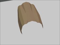
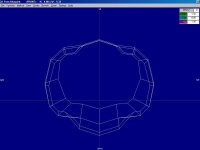
The screenshots show my first attempt at Coolant Radiators for the Lightning-F. From most angles, they look narrow, but actually match photographs pretty well.
Unfortunately there are not many photographs of early model Lightnings except for Glacier Girl which is a P-38F-1-LO.

- Ivan.
 

Attachments

  • RadiatorCompare1.jpg
    RadiatorCompare1.jpg
    25.8 KB · Views: 0
  • RadiatorCompare2.jpg
    RadiatorCompare2.jpg
    27.8 KB · Views: 0
  • RadiatorCompare3.jpg
    RadiatorCompare3.jpg
    31 KB · Views: 0
  • RadiatorCompare4.jpg
    RadiatorCompare4.jpg
    15.9 KB · Views: 0
  • RadiatorF-WireFront.jpg
    RadiatorF-WireFront.jpg
    38.5 KB · Views: 0
  • RadiatorCompare5.jpg
    RadiatorCompare5.jpg
    51.5 KB · Views: 0
One of the biggest problems with building a Radiator for the F model Lightning is the inability to find good detailed drawings. Photographs are also hard to come by if they are not of "Glacier Girl".
Because of those issues, the new Radiator was built mostly by eyeball with as many photographs as I could find but all the large photographs are of Glacier Girl.

While I believe that Glacier Girl is a very pretty restoration, just about everything was rebuilt rather than original, so I do not have as much faith in the contours of the sheet metal. Unfortunately, there are no other early model Lightnings flying today and even photographs of static displays are hard to find.

The Radiator shown here is actually a touch wider than the last one but note that it is still much narrower than the one for the J model.

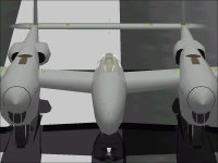
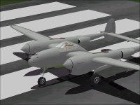
Attached are screenshots of the Lightning with an early model Radiator on the Port Side and the late model Radiator on the Starboard side. They look about right to me, but I make no great claims to accuracy because of the "Eyeball" measurements.

Please feel free to comment if you see inaccuracies.

- Ivan.
 

Attachments

  • RadiatorFtoJ1.jpg
    RadiatorFtoJ1.jpg
    43.4 KB · Views: 0
  • RadiatorFtoJ2.jpg
    RadiatorFtoJ2.jpg
    55.1 KB · Views: 0
  • RadiatorFtoJ3.jpg
    RadiatorFtoJ3.jpg
    47.8 KB · Views: 0
  • RadiatorFtoJ4.jpg
    RadiatorFtoJ4.jpg
    36.5 KB · Views: 0
  • RadiatorFtoJ5.jpg
    RadiatorFtoJ5.jpg
    49.7 KB · Views: 0
  • RadiatorFtoJ6.jpg
    RadiatorFtoJ6.jpg
    27.5 KB · Views: 0
Back
Top