Maty, I will also look for some 3-views for you with cross sections.Honestly, the whole thing just frustrates me a lot due to lack of reliable reference. Does anyone in this forum live near Tucson and if so, is anyone willing to take a few pictures of the inside for me? Cause I tried contacting the museum, and I tried contacting the Navy library mentioned in this thread, and I even tried contacting the guy who designed Minicraft's 1/72 scale model, since he has a 3d model of it, but every single time the e-mail fails to send. Is it a browser related problem? Cause I'm using chrome and whenever there's a link to send an e-mail it doesn't work and I jsut copy the e-mail address and do it through gmail.
-
There seems to be an uptick in Political comments in recent months. Those of us who are long time members of the site know that Political and Religious content has been banned for years. Nothing has changed. Please leave all political and religious comments out of the forums.
If you recently joined the forums you were not presented with this restriction in the terms of service. This was due to a conversion error when we went from vBulletin to Xenforo. We have updated our terms of service to reflect these corrections.
Please note any post refering to a politician will be considered political even if it is intended to be humor. Our experience is these topics have a way of dividing the forums and causing deep resentment among members. It is a poison to the community. We appreciate compliance with the rules.
The Staff of SOH
You are using an out of date browser. It may not display this or other websites correctly.
You should upgrade or use an alternative browser.
You should upgrade or use an alternative browser.
Thanks for the kind words, man. Anyway, I decided to not start over from scratch on the nose again (Way too much work put into the interior) and instead fix anything that really looked odd. After a bit of research, turns out the problem was I had modeled the smallest bulkhead wrong. It not perfect now, but it is a lot better.Maty, you done such a great job so far maybe take a day or so away and come back when you're ready. The fact is to the vast majority of us, the shots we've seen in Blender look fabulous.
Sorry, but I have no clue what you just said.PBM-5A Mariner for FSX Game start?
Sorry, but I have no clue what you just said.
oh.. yeah.. And How about the PBM-5 Mariner?
It's doing fine, haven't really touched it in two days.oh.. yeah.. And How about the PBM-5 Mariner?
It's doing fine, haven't really touched it in two days.
Yes, yes! I did not touch
I'm saying I didn't touch it.Yes, yes! I did not touch
I'm saying I didn't touch it.
Yes, we know.
Roger
Senior Administrator
How's the PBM-5A Mariner coming along?
tjsdn1375 as you don't seem to read pms will you stop asking Maty, everyday how the project is coming on! Maty is at a difficult stage with his design and doesn't need you to be asking every day how it is progressing.
Roger.
tjsdn1375 as you don't seem to read pms will you stop asking Maty, everyday how the project is coming on! Maty is at a difficult stage with his design and doesn't need you to be asking every day how it is progressing.
Roger.
Yes ma'am, I'm sorry. The project I thought it would not coming.
Hey, guys, I realise this may be a bit of an odd question to ask, but in order to simulate the aircraft realistically in beamng (The game I'm almost done programming it for) it's very hard to distribute weight realistically, but I've basically come up with a way. Anything to the front of the center of gravity should weight the same as everything behind it, and anything to the left of it the same as anything on the right. The thing is I don't really know where the COG is supposed to be. The flight manual specifies it as forward 25% MAC, can anyone tell me where exactly that would be?
Hey, guys, I realise this may be a bit of an odd question to ask, but in order to simulate the aircraft realistically in beamng (The game I'm almost done programming it for) it's very hard to distribute weight realistically, but I've basically come up with a way. Anything to the front of the center of gravity should weight the same as everything behind it, and anything to the left of it the same as anything on the right. The thing is I don't really know where the COG is supposed to be. The flight manual specifies it as forward 25% MAC, can anyone tell me where exactly that would be?
Maty,
The wing root at its widest point at the fuselage (ignore the fairing) is called the wing root chord. At the tip of the wing (minus the wing cap) is the tip chord.
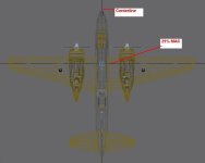
25% Mean Aerodynamic Cord = 1/4 width of the wing root at the fuselage (exclude the fairing) and 1/4 the way back from the leading edge of the wing.
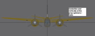
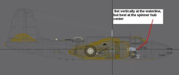
For sim purposes, it usually works well to set the aircraft in your design program with your grid on, with the aircraft placed at center line laterally, near the waterline vertically, and at 25% MAC longitudinally.
When you set up your weights for fuel and cargo, the CoG will change with your weight distribution. That will come when you do the flight modeling (FDE).
See my attachments for my approach.
By setting the aircraft this way, in the aircraft.cfg, set the FS Reference point at 0,0,0 coordinates. This is the cross-hairs of your design world and I usually set the CoG the same. Now you know exactly where you are with the aircraft.
Coordinates for the fuel tanks, engines, main and center gear, pilot, cargo weights, lights, etc are now based from there and you can get those coordinates from your design program to plug into the aircraft.cfg.
Coordinates forward of the reference are positive numbers; and right of the reference are positive numbers. Anything to the rear or left are negative numbers.
Just FYI, nose geared aircraft normally carry less than 20% of the weight with mains carrying 80%+ of the weight.
Aircraft design limits how far from 25% MAC you can stray, usually in the 18% to 30% range. You should be able to find those restrictions so you can set up your flight model accordingly. If you stray outside those limits, the elevator authority will not be able to maintain level flight or get you off the ground.
Gear position relative to CoG/FS Reference is critical as well as it impacts weight distribution and your ability to "rotate" at proper speeds. Get those coordinates from a vertex at the bottom center of the tires.
Attachments
To add to what Milton said as an aside out of interest:
The 0.25 MAC (or you might see a barred c) comes from the location of the aerodynamic centre of the wing. The aerodynamic centre is also known as the zero moment point, the imaginary point where the lift of the main wing acts from. Using it as a datum helps make your trim calculations easier as you can mostly ignore lift.
The 0.25 is an estimate for a wing in the incompressible region of flight, and there it's really very accurate, as you get closer to Mach 1 and pass the sound barrier the location of the aerodynamic centre moves, to roughly 0.5 MAC, hence Concorde's trim tanks.
The he importance of the CoG in relation to the aerodynamic centre is to do with pitch/longitudinal static stability, what happens when an outside influence disturbs the aircraft in steady flight. If the centre of gravity, where the aircraft rotates about, is inline with the ACentre a change in pitch will cause a change in lift, but no pitching moment. If the CoG is behind the ACentre a change in pitch will cause a change in lift, which causes a moment that increases the pitch and so on, that's static instability. For statically stable aircraft, the CoG is ahead of the ACentre and the pitch causes a moment in the opposite direction, causing the aircraft to return to level flight.
(What do you know, I do remember mechanics of flight! I hope that's interesting info!)
To add to what Milton said as an aside out of interest:
The 0.25 MAC (or you might see a barred c) comes from the location of the aerodynamic centre of the wing. The aerodynamic centre is also known as the zero moment point, the imaginary point where the lift of the main wing acts from. Using it as a datum helps make your trim calculations easier as you can mostly ignore lift.
The 0.25 is an estimate for a wing in the incompressible region of flight, and there it's really very accurate, as you get closer to Mach 1 and pass the sound barrier the location of the aerodynamic centre moves, to roughly 0.5 MAC, hence Concorde's trim tanks.
The he importance of the CoG in relation to the aerodynamic centre is to do with pitch/longitudinal static stability, what happens when an outside influence disturbs the aircraft in steady flight. If the centre of gravity, where the aircraft rotates about, is inline with the ACentre a change in pitch will cause a change in lift, but no pitching moment. If the CoG is behind the ACentre a change in pitch will cause a change in lift, which causes a moment that increases the pitch and so on, that's static instability. For statically stable aircraft, the CoG is ahead of the ACentre and the pitch causes a moment in the opposite direction, causing the aircraft to return to level flight.
(What do you know, I do remember mechanics of flight! I hope that's interesting info!)
Well stated Firebar; thank you
Mariner's still progressing, sorry for the lac of updates, I just got A2A's B-17 and let's just say it keeps me busy (And very entertained). Anyway, the nose section's nearly finished. Here's a picture of the levers that control the bomb window covers:
The only thing missing from the nose compartment now are some of thee bulkheads for the top section (The one that's usually replaced with a turret), the door and the anchor (for the stripped-down variant).

P.S. Milton, love those shots of the A-20. Not just because of their usefulness, but because they're the first pictures of your A-20 with gear up and landing lights added.
The only thing missing from the nose compartment now are some of thee bulkheads for the top section (The one that's usually replaced with a turret), the door and the anchor (for the stripped-down variant).

P.S. Milton, love those shots of the A-20. Not just because of their usefulness, but because they're the first pictures of your A-20 with gear up and landing lights added.


