Warhawk

Ivan

Charter Member
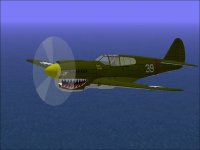
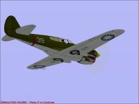
I originally built a P-40E and released it in January 2005.

Since then, it has had a couple slight modifications such as improved exhausts.
Some of the parts were re-used to make the P-40C aircraft.
The idea of making a long tail version (P-40K, P-40M) is the first real "modification" to the basic design.
Attached are some screenshots illustrating the differences.

There is still something not quite right about the shape of the Tail Fin and I believe the panel lines need some additional attention, but it seems to fit together fairly well at this point.

- Ivan.
 
Design Choices

Sometimes design choices for the original project (P-40E) cause problems when trying to modify it into a new project.

In this case, the scale of the Fuselage was consistent across files but a little odd at 11.6 feet to 256 pixels.
This makes aligning textures a bit difficult in certain circumstances. The lack of a camouflage pattern on this aircraft makes this not terribly important, but if I were to repaint with a pattern extending across different parts of the aircraft, precise work may be difficult.

Another issue was that the textures were laid out VERY tight within the files so that for a 20 inch longer tail, there needed to be at least one more texture file because the extended parts would not fit onto the same files.
There also wasn't room to texture any additional parts using the existing files.

These days, I am a bit smarter and don't lay things out quite as tight because using an additional file may simplify the matching of parts pairs such as landing gear, guns, etc.
The assembly sequence was also a touch strange at places, but I chose not to change things because the original sequence was working well enough.
Many parts were reshaped from just aft of the Cockpit, but the parts count is identical to the original which I believe is rather amusing.

The Curtiss Company designation for the P-40E and P-40K were the same; both were Hawk 87B's.
Next comes the new markings.....

- Ivan.
 
Matching Shapes

I created the P-40E from a set of drawings by William Wylam.
These were drawings derived from Curtiss company specifications for the aircraft with dimensions stated.
I had noticed when building the model that sometimes the stated dimensions could not actually line up, but the differences were not great and the result looked like a short tailed P-40.
I had also noticed that my model differed a bit from photographs but wasn't quite sure where the differences were.

Attached are two images derived from overlaying the wire frame from my model with a drawing and a photograph.
There is of course the possibility that the photograph isn't lined up, but the differences are a bit more extreme than a slight misalignment would create.

The interesting thing is that the mismatch does not appear in the Fin as I was expecting. It is mostly in the Canopy and Keel area.

The big question now is whether or not I should continue trying to develop this model or not.
The Wylam drawing is the only dimensional reference I have at this point and my model agrees pretty well with that.

What do you all think of the mismatches?

- Ivan.
 
Ivan,
I do see the difference you are talking about, BUT I can not help looking at the shadows under the wings. If the shadows were lined up
that may compensate for a lot of what we see. Do you think ?? I am just not so sure that you are that off of the mark.

Dave
 
as always, the decision to change
or live with the discrepancies is up to you.

as my wife likes to say when i point out project deficiencies,
nobody would notice, if you didn't say something.

but, then again, it's your project.
not hers.
 
Reference Drawings

Hello Smilo, No Dice,

To me, the shape of an aircraft model is very important. It isn't enough to get a general representation, at least not for me.
It has to have "The Look". This one just doesn't quite look right at this point.

I went back to check the drawings I was working from (by William Wylam). The drawing lengths add up about 4 inches short of the stated length of the aircraft. The greatest deviation from the stated measurements was around 1/2 inch at the rear of the keel fairing. So.... From the dimensions I have, it is "Correct".

So now what?
- Ivan.
 
Ivan, I can see your point, but from one who can barely keep the things flying I would be very happy with it 'as-is'. BUT...knowing me as I do, if I were in your position and spent the hours you have in developing it as far as you have I would not be able to stop until complete satisfaction is achieved.

Unfortunately, I do not have the ability to build anything at all so the notes you have produced are going over my head a lot better than the planes I fly!

If I had not been privvy to this thread the A/C would have looked brilliant; and now you have shown me the tiny inaccuracies that exist I can honestly say to me it makes no difference....but I am not Ivan.

In a small way that makes me glad as I do not have to worry.

As the Irishman once said; 'I'm just grateful for small Murphys'.

I would love to be in your position but glad I'm not!

Best wishes,

Graham.
 
Thanks Arfyhun,

Last night I had a bit of trouble sleeping and I found an aircraft diagram of the P-40N in the book America's Hundred Thousand. The odd thing abour this drawing is that it has a scale below the drawing showing distances from the aircraft datum line which happens to be about 1/3 of the way back on the spinner from the tip.

I spent about an hour or so using a clear straight edge and measuring the locations of various aircraft pieces from the reference line. This morning, I took those measurements and compared them to the P-40K that I have been building.

Surprise, surprise, there isn't an item that is more than about 1/2 in off on my model as compared to the drawing except for the rudder hinge line and I already knew about that.

So now I can honestly say that I have not a clue as to where the problem is except that it does not match photographs....
Still looks wrong but I have no idea where to fix things.

- Ivan.
 
just a guess.
is it possible that the photograph perspective is off?
i have a hard time imagining that the photo view angles
are as precise as a, say, side view drawing.

it would seem to me, that a slight variance in the view angle
would change the perceived part distance.

especially for parts farthest from center,
ie; tail parts would appear to be farther from center
than they would be in a flat drawing.

build the model to drawing specs...no small task,
load it up, go into spot/chase view and pan around.
how does the tail look when viewed from slightly forward/up and down?

then there is the monitor resolution variations.
but, that's another subject all together.
 
Thanks for the insight, Smilo.

I pretty much have finished the visual model, but it just doesn't look quite right.
The Chinese insignia will be replaced with standard USAAF stars of a style suitable for late 1942.
The fuselage stars will displace the tactical number and there will be few additional markings.

This is such a common aircraft that I am surprised that even the drawings don't agree with each other.
Since I don't have a good drawing to work from, I can't really make reasonable adjustments.

There were some problems with the Wylam drawings:
The stated overall length was 31' 7".
The sum of the lengths of all the parts was only 31' 3", so in order to use the dimensions, I had to arbitrarily add the extra 4 inches SOME PLACE on the aircraft. I did this by adding an inch here and there an eyeballing the result.

Another issue is that the book "America's Hundred Thousand" specifies the K and N models as being 33.22 feet.
The P-40N Erection and Maintenance Manual specifies the length as 33 feet 3.7 inch. Yet another source claims the length to be 33 feet 3.75 inch or 33 feet 4 inch.
I will probably use the number from the E&M manual because I believe those tech manuals the most against the other sources.

Still wondering which is right.

- Ivan.
 
Ivan, I can only say that when you come to your final decision the Hawk will look brilliant.

Don't lose sleep, take a deep breath and 'amble along'. I'm sure that way all things will fall into place.

Oftentimes, it's the tension inside which gets in the way. Easy for me to say, I know!

Ask your son which looks better, a lot of times a fresh pair of eyes can see the wood for the trees.

Good luck,

Graham.
 
Over the last week or so, I decided to finally revisit the P-40 Long Tail.
I started with a dimensional confirmation of the original Short Tail version of the P-40E and found that apparently I had misread Wylam's Drawing. The dimensions actually don't have a 4 inch discrepancy if it is interpreted correctly. I also found that my P-40E is a bit off in places but generally close enough to the drawing not to matter much (about 3/4 inch off at the worst and generally under 1/4 inch off or dead on).
I also found that my copying of the panel lines around the Rudder and Fin area was quite poor.

The Long Tail configuration that I am building as a model looks like either a late P-40K or P-40M. The E&M manual lists 33 ft 3.7 in, so that would make it 20.7 inches longer.
In looking over a LOT of photographs, it finally occurred to me that I had handled the Fuselage Extension incorrectly:
Yes, it is 20.7 inches longer, but there is also a vertical shift that isn't so precisely defined.
Another VERY interesting thing is that the Rudder has the exact same visual appearance between the two versions!
Most of the panel lines on the Fin also appear to match with that exception that there is a new panel at the root of the Fin which apparently extends it.

Extending the Fin upwards made it look more proportional but also made it not fit into its original texture file. This little change cascaded through a couple texture files because now the Tail Cone also needed moved which affected the Landing Gear.... While updating textures, I found that the Rudder had an incorrect number of Ribs and didn't match the real aeroplane's hinge lines.
Another major change was that the Razorback area behind the Cockpit apparently had a subtle bump which I also added. (It is now around 2 scale inches higher which changed all the contours in the Aft Fuselage. The wider and higher Aft Fuselage also affects the Quarter Windows, Framing and the cutout underneath. Without going into even more detail, the changes and fixes took 3-4 evenings....

The changes are not entirely obvious and I am sure they still disagree with photographs, but they do seem to agree with the drawings and have "The Look" I was trying to get.

- Ivan.
 

Attachments

  • Hawk87B_LF.jpg
    Hawk87B_LF.jpg
    44 KB · Views: 0
  • Hawk87B_RALow.jpg
    Hawk87B_RALow.jpg
    36.7 KB · Views: 0
looks very good.
nicely done.

Thanks Smilo, I didn't want to respond before I actually had completed something substantial on the project.

The Tail got yet another redesign. It is entirely by eyeball at this point and a couple polygons were added to the leading edge of the fin. The textures are redone a bit to look more like the actual aircraft. The first SCASM pass has been done to the model and it should make future texturing easier. An interior view of the canopy framing for the virtual cockpit has been built but it hasn't been textured yet. The nice thing is that the canopy framing is identical between the E, K, and M models so it only needs to be done once for those aircraft. The frame still needs to be flipped inside out after disassembly to SCASM. Quite a lot of effort goes into the model that isn't even visible from an external screenshot.

- Ivan.
 
Thanks Smilo.

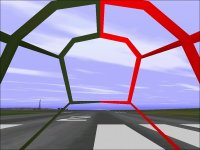
Here's the process I am using:
1. I copy all the pieces from the Canopy Frame Component (CFrame-something).

2. I then narrow them down a bit (50% in this case) so that they will not block too much visibility from the cockpit (to be discussed later).
At this point it is an untextured Component (IFrame) which I modify to remove bleeds and sparklies where the pieces don't quite meet up.

3. Next it is textured to be Dark Green. One side is textured Red for better visibilty for the screenshot.
When it is textured and changed to be a "Smooth" AF99 Component, it disappears from the Interior View.
The Red is easily seen against the real canopy frame to show how the widths compare.

4. Now HERE is the cool part: Next, I extract the SCASM code for the Component and run it through a little C program I wrote which reverses all the Polygons directions.
The result is a "Component" which faces inward and isn't visible from outside. Editing the SCASM code by hand would take a couple hours with great potential for error. Using this conversion program takes about 2-3 seconds!

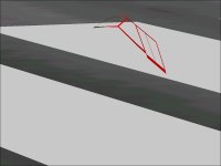
The result is amusing to look at. The Exterior View screenshot shows the Canopy Frame looking like it is facing you 7 or 8 o'Clock.
In Reality, it is facing 10 or 11 o'Clock along the same direction as the runway markings.

....
 

Attachments

  • IFrame.jpg
    IFrame.jpg
    48 KB · Views: 0
  • IFrameExteriorView.jpg
    IFrameExteriorView.jpg
    27.1 KB · Views: 0
  • IFrameInteriorView.jpg
    IFrameInteriorView.jpg
    59 KB · Views: 0
i wish i could come up with
a comment besides my standard,
very nice or that's cool, but for now,
it will have to do.

thanks for the shots.
 
Hello Smilo,

Actually I like your responses because I am sure that if you saw something that didn't look quite right, you would tell me. Hubbabubba also can be counted on for an honest critique.

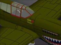
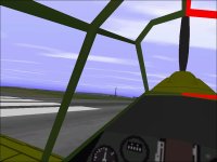
Here is what happens when the Internal Canopy Frame gets put into the rest of the model.
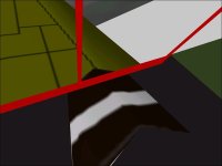
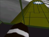
There is a slight problem though because the Canopy Frame then chops off part of the Pilot's Shoulder. The P-40 has a very low Cockpit Wall as compared to many other aircraft. One pilot remarked that it felt like the glass came down to around your waist.
The solution after leaving it overnight was simply to redraw the Pilot's Shoulder yet again.

Since I took these screenshots, I increased the width of the front section of the windshield frame by 50% and it looks a bit better to me now. I also adjusted the display range of the Flaps and Flap Wells so that continue to display until fully retracted. I had to do a little guessing here and also to remove the entire model except for the Flap parts to see what was actually happening when all the parts opened and closed.

Perhaps I am terribly out of practice, but flying this beast is a bit more difficult than I remembered. It also changes Directional Trim with Airspeed changes like the actual aircraft does though I didn't intentionally do this. Another goofy thing is that CFS doesn't have lockable Tail Wheels so there is lots of overcontrol at low taxiing speeds.

- Ivan.

- Ivan.
 

Attachments

  • IFrameCombined.jpg
    IFrameCombined.jpg
    51.5 KB · Views: 0
  • IFrameOuch.jpg
    IFrameOuch.jpg
    29.1 KB · Views: 0
  • IFrameBandAid.jpg
    IFrameBandAid.jpg
    33 KB · Views: 0
Back
Top