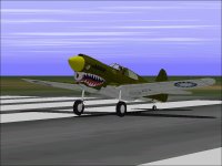
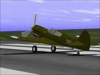
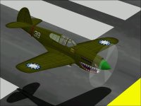
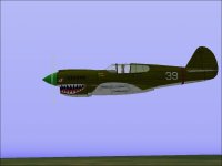
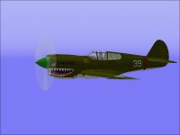
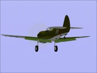
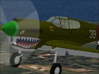
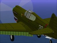
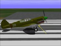
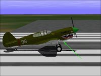
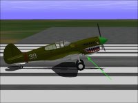
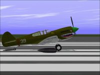
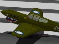
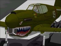
Warhawk

Template Parts and Checking Alignment

We got back from vacation this weekend.

While on vacation, I had quite a bit of time to look for photographs of the P-40 and found quite a few though I did not have the capability to actually do any modifications to my project.

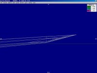
One of the things I noticed was that the P-40 actually had a wing tip with a flat underside and I had missed that completely in my model. This is actually a very easy and quick fix which I did the night we got back.

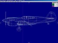
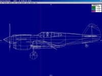
Other changes have been from starting from the wing trailing edge and moving forward. (I believe I have completed everything behind the wing.) My process here is to rework the reference parts (the equivalent of Jigs and Fixtures) while checking how they align with other existing pieces and THEIR Templates which may also get reworked.

An interesting thing to observe is the relationship between the cowl fairing on the bottom of the fuselage and the line of the lower fuselage as it continues back to the rudder. On the real aircraft, the underside of fuselage at the cockpit is where the two wings are joined to be covered by a fairing. On my model, this line is just imaginary because there are no actual polygons under the fairing. The light blue reference part shows a fairly consistent line between the tail and the cowl and is used to confirm that the polygons forming the wings are aligned with the wing fillet polygons and their projected endpoints are in alignment at the fuselage centerline. The cowl fairing polygons must also meet along the projected line.

Next step is to rebuild the front half of the Warhawk....

- Ivan.
 

Attachments

  • P-40NewWingTip.jpg
    P-40NewWingTip.jpg
    29 KB · Views: 0
  • P-40ReferenceCompare.jpg
    P-40ReferenceCompare.jpg
    51.3 KB · Views: 0
  • P-40RebuildCurrent.jpg
    P-40RebuildCurrent.jpg
    51.6 KB · Views: 0
The rework of my P-40E is finally nearing completion. It turned out to be MUCH more extensive than I had first expected.

As an example, the last thing I found which was only a couple days ago was that the maximum fuselage width was quite a bit off.
William Wylam's drawing lists it as 1' 9" (1.75 feet in AF99 Units) from the centerline.
I had already done a correction (to 1.66 feet) some time back because it simply didn't look right
When I reworked the radiator intake (Shark Mouth), the shapes still didn't look right.
I found that I had a pretty good technical drawing and re-scaled it down to 1 pixel = 0.01 foot.
The tech drawing showed a maximum width of 1.60 feet and an upper cowling that was also 1.60 feet above the propeller centerline.
This is very unlike the Spitfire or Mustang that do not have constant radii in their cowling.
A P-40N Erection & Maintenance manual lists the fuselage maximum width as 38.3 inches in a 3-View drawing and 38.32 inches in a dimensions table.
38.32 inches overal width works out to 1.5966667 feet from the centerline.

Seems like a pretty reliable number to me!

At this point, I have most of the polygons reworked. There are a couple wing polygons and the pilot and canopy that haven't been changed and that is about it! This turned out to be more work than building an entirely new design.

Next comes the texturing and animations and minor revisions to the AIR file.
The screenshot shows a rather disturbing state I saw earlier.

- Ivan.
 

Attachments

  • BrokeSomething.jpg
    BrokeSomething.jpg
    46.1 KB · Views: 0
Latest changes were the following:
Added Gun Ports to the model. They were only a texture before. They should be stubs but are just black ports. The locations (offset from centerline) came from the P-40N E&M manual.

Modified DP file to match the new outline of the model. Relocated the weapons slightly to match the locations from E&M manual. Changed the bomb load from 1x500 lb to 3x500 lb. There are still a few more things to check here.

Modified the AIR file for new contact points for the longer landing gear struts. Moved the propeller location about 1 inch up and 1 inch forward to match the model which hopefully matches the tech drawings.

Next comes a majpr rework of the layout of textures and some edits to the textures themselves.

So far, I can say that with the same paint job and even knowing where to look, I don't see much detail difference other than the increased depth of the aft fuselage. The entire cowl is about 1 or 2 inches higher, but it isn't very obvious. The 1.5 inch narrower fuselage isn't very obvious either.

I have been changing the painting templates and from those, it becomes apparent that somewhere around 95% of the polygons were altered and for components of the aircraft, it is closer to about 98%.

- Ivan.
 
After about three evenings of relocating textures and panel lines, here is what I have.
A wire frame comparision shows LOTS of changes, but a screenshot doesn't show up much difference at all.
I suppose the comparison is to that of an "Eyeball Scale" model versus a dimensionally correct scale model.

Still need to relocate some textures, but the basic shapes are done. The dimensions and layout are as accurate as I can make them with the information I have accumulated with the exception of the area just behind the radiator exhaust.

Besides the visuals, there is plenty more to do. I figure this beast deserves to have the WEP rating that I didn't know about when I first built it way back.

- Ivan.
 

Attachments

  • WarhawkRebuild_LFLevel.jpg
    WarhawkRebuild_LFLevel.jpg
    55.1 KB · Views: 0
  • WarhawkRebuild_LALevel.jpg
    WarhawkRebuild_LALevel.jpg
    53.9 KB · Views: 0
Hello All,

The rebuild is pretty much finished. I am not quite satisfied with the shape of the Radiator Exhaust, so that area will get rebuilt again. Besides that, there are a couple panel lines that need to get moved around a bit after the polygons under them got shifted.

In looking at the screenshots, I KNOW that just about everything on this aeroplane got moved around, but the general appearance does not appear to have changed much at all. The shape of the Radiator Intake took a few tries. I finally decided to open a Otaki (?) 1:48 P-40E model kit I had to see how the shapes looked in 3D. I believe I got the shape fairly close to the model. Hopefully it is close to the actual aircraft.

The only new obviously new thing is the textured Radiators.

- Ivan.
 

Attachments

  • Warhawk)_RFHigh.jpg
    Warhawk)_RFHigh.jpg
    49.7 KB · Views: 0
  • Warhawk_LProfile.jpg
    Warhawk_LProfile.jpg
    28.8 KB · Views: 0
  • Warhawk_Radiator.jpg
    Warhawk_Radiator.jpg
    59 KB · Views: 0
  • Warhawk_RadExhaust.jpg
    Warhawk_RadExhaust.jpg
    81 KB · Views: 0
she's a real beauty.
nicely done.

at the risk of sounding like an obnoxious ***,
have you considered bringing the project full circle
and building the p-40 precursor, the p-36 hawk?

might be interesting.
 
Hi Smilo,

Thanks for the suggestion.

Actually I have had a P-36 / Hawk 75 project going for a couple years now.

From my line of reasoning, after I had the first P-40E (the current "Warhawk" project), I thought there would not be too many changes to get to a P-40C.
It turned out to a LOT of changes to get to a P-40C "Hawk 81" project. (Fewer though than my current revisions to the Warhawk.)
From the Hawk 81, it should have been "easy" to get to a Hawk 75 since everyone KNOWS the P-40 was just a P-36 with a new engine. Turns out that there aren't that many shared pieces between the two. Although the general construction is the same, everything was moved around a bit to put the Allison inline in place. The prototype P-37 and P-40 might have been simple engine swaps, but production stuff was a lot dfferent.

The cockpit is located in a different place. The main gear fairings are different. The tail gear is also located differently.
Internally, even the fuel tanks are quite different. There may be more that I haven't seen yet.

I COULD re-engine a P-40C and get something looking a lot like a P-36, but dimensionally it would be quite wrong. I am also not sure the Paul Matt drawings I have are correct.

With the latest drawings on the P-40, I could probably get a bit further than I have before though. It at least gives a common reference point between the different airframes.

The idea of this "Thorough Rebuild" was to get to a good point for further P-40 releases though I will probably change direction again before that happens because I don't have a very long attention span.

- Ivan.
 
Revised the Radiator Exhaust to look more like the real thing.

I also found a pretty serious bleed in the nose from an "improvement" I had made.
Turns out I usta be a bit smarter than I am now.
After removing the bleed, I'll need to adjust the textures on the parts that were reshaped.

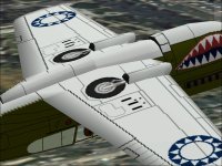
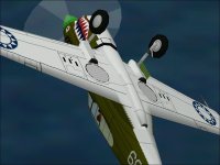
The remaining screenshot shows the revised wingtip.

- Ivan.
 

Attachments

  • Warhawk_NewFairing.jpg
    Warhawk_NewFairing.jpg
    57.4 KB · Views: 0
  • Warhawk_LLow.jpg
    Warhawk_LLow.jpg
    36.9 KB · Views: 0
  • Warhawk_Wingtip.jpg
    Warhawk_Wingtip.jpg
    27.3 KB · Views: 0
'twas just a thought
inspired by an Aviation History article
about the USS Ranger based F4F Wildcats
taking on Vichy French H-75A Hawks
during Operation Torch in November 1942.

was almost considering setting up
invasion Task Force 54 off Morocco.

oh well...sorry to interrupt.
back to topic.
 
Hi Smilo,

That discussion seemed very much ON topic to me. The Hawk 75 is a natural progression when working on the P-40. It seems less and less likely now that I will actually do a P-40Q. It just seems like way too much work and is a hard thing to comtemplate when I have spent the the last few weeks essentially building a new P-40E that looks almost exactly like the original one. I felt I needed to do that to own a really "Good" P-40 which I have always wanted.

If I am planning on building more P-40s I needed to have as good a starting point as I can create.

Another thing to consider is that just about all of this group of fighters has the same basic wings, stabilizers and fin though the pieces get moved around a bit. With that in mind, hopefully the next Curtiss fighter project will just be a matter of moving a few correctly dimensioned pieces around and connecting the dots.

Status update:
After the last post, I was thinking this aeroplane was ready for the SCASM treatment. I started the process and then decided to check on JUST ONE MORE THING....

As Background:
Although this P-40E has almost everything altered from the original to one extent or another, the build secquences and file naming are nearly all the same. The actual parts themselves sometimes are simply moved or hava vertex moved or have nothing of the original except for the purpose.

To cure bleeds, I often duplicate the same part in several assemblies. When the part is re-shaped, it sometimes doesn't fit in all of the original assemblies any more. Also, AF99 has a single directional display polygon called an "insignia". These work pretty well for addresing specific bleeds.
The problem is that if a part is reshaped, often the insignia parts display in the wrong direction. You don't even need to change the sequence of vertices. Now, you have a bleed from a direction that you were not checking to build the new part or the insignia part itself becomes a bleed because it is facing the wrong direction.

Glue (viewing planes) are also very often located in reference to existing parts. When those parts are re-shaped or moved, sometimes the glue part itself needs to be re-shaped.

Another issue is that all the rebuilding adds up to quite a few more polygons. At the moment, I am up from 1042 ro 1112. When the parts count gets higher, sometimes AF99 starts to behave badly.

....
 
The first screenshot shows the main gear struts bleeding through the flaps. Note that the same thing is happening from the far side strut as well. A workable solution in the original model was to add flap parts to the landing gear but as insignia displaying up and aft. When the flaps were reshaped, the insignia flipped to facing forward and down which made them useless. When a couple extra parts were added in other areas and the insignia direction was flipped, the texturing here completely fell apart. I ended up removing the pieces because with the texturing incorrect, it was worse than the bleed it was trying to cover up.

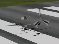
The second screenshot shows a couple of the reasons for the extra parts count. The spinner on a P-40 doesn't really come to a sharp point. The end is spherical with a 1.5 inch radius. Adding one more section to the spinner structure added 12 polygons. Building the wing guns as parts rather than as texture added one more part for each gun and one for glue to attach each one to the wing.

The third screenshot shows a notch or cutout at the trailing edge of the flaps. The flap on each side is made up of 4 separate parts. To have a cutout like this on a textured piece generally requires at least 3 parts. The earlier Warhawk had the inboard edge of the cutout aligned with the join between wing and fillet.
The wing / fillet join needed to be moved slightly 0.15 foot inboard to cure another bleed and required that an additional part be added to the flap on each side along with the glue part to locate it.

I don't know if I found all the issues yet....
- Ivan.
 

Attachments

  • Warhawk_FlapBleed.jpg
    Warhawk_FlapBleed.jpg
    26.8 KB · Views: 0
  • Warhawk_Spinner.jpg
    Warhawk_Spinner.jpg
    62.3 KB · Views: 0
  • Warhawk_FlapNotch.jpg
    Warhawk_FlapNotch.jpg
    52.6 KB · Views: 0
The front of the landing gear fairings got a bit of a rework to cure a small sparkly where the panels did not overlap.
I finished the SCASMing this morning and adjusted the collision bubble. I did some minor texture tweaks this afternoon also. It seems like even some of the references I am using do not agree with photographs. The photographs are guaranteed accurate, but don't show enough detail to get all the major panel lines.

Sometimes for animation tests, it helps to have a slow computer so that the transitions don't just flash by.

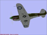
This afternoon, my 10 year old nephew took it for a fighter intercept mission. I believe he was chasing B-17s. The sim remains paused on one of the game machines in the living room.

- Ivan.
 
War Emergency Power

The military rating for the V-1710-39 was 1150 HP at Sea Level with a Manifold Pressure of 45.5 inches Mercury.
In the last releases of this aeroplane, I had not included any War Emergency Power but since then, I have found a manual that does give a WEP rating. In addition, there is the document from Allison which permits up to 60 inches Mercury on the -39 engine.

The aircraft manual gives the WEP rating as 1470 HP at Sea Level with MP of 56 inches Mercury. In preparation for tweaking, I first added the WEP change to the AIR file and bumped the critical altitude (I don't this field does anything) down to 12,500 ft. Since it is pretty much impossible to actually test at Sea Level, I run at a minimum altitude of 500 ft for consistency. Generally this means that the engine power will be around 5 HP or so above the SL rating.
I was a bit surprised when the first test showed 1487 HP which is close enough for my purposes. All that remains is checking the power at each altitude and conducting a bunch of performance tests.

Sometimes we get lucky.
- Ivan.
 
Radiator Fairing

Although the latest version of the P-40E is more dimensionally correct, there was something about the look that was not as good as the original.
I believe that tonight I fixed one of the issues.

It isn't easy to see and depends a bit on the angle of the photograph, but there is a very slight rounding of the underside of the Radiator Fairing before forward of the cooling flaps. The open flaps often disguise this because with the flaps even slightly open, the underside looks quite flat.

Fixing this added another 4 Parts to the project
Unfortunately, the textures also needed a slight modification and the Animation needed to be redone.
The worst part is that this aeroplane needs another trip through the rather tedious SCASM process.

- Ivan.
 

Attachments

  • TooFlat.jpg
    TooFlat.jpg
    54.5 KB · Views: 0
  • Rounded.jpg
    Rounded.jpg
    53.1 KB · Views: 0
Carburetor Scoop

There was something about the shape of the Carb Scoop that bothered me.
I believe this version is a bit closer to the actual shape. It may not show it, but I spent a bit over two hours building and re building to see if I could get the shape the way I thought it should be.
I don't know how good of a match it is now, but it looks closer to me.

I was wondering why I was having such trouble staying on the runway at take-off.
After a few tries, it finally occurred to me that the issue was mostly my lack of understanding:
We all know that steerable tail wheels (which the P-40 has) do not lock in CFS.
As such, they are VERY sensitive at the start of the Take-Off run.
As soon as the Tail Wheel lifts, the torque swing must be counter-acted by the Rudder.
I was not catching the change quickly enough. When I did catch this, I found that very little Rudder input is required to hold the aeroplane straight while in reality, there should have been barely sufficient control.
Next task is to reduce the control effect at low airspeeds.
Elevator control seems too high as well.

- Ivan.
 

Attachments

  • Rounded.jpg
    Rounded.jpg
    53.1 KB · Views: 0
  • P-40E_CarbScoop.jpg
    P-40E_CarbScoop.jpg
    51.5 KB · Views: 0
Hi Ivan,
Your Warhawk not only looks really cool with interesting details, but also flies with lots of character - quite a challenge!
Nice work!
Cheers,
Aleatorylamp
 
Thanks Aleatorylamp,

The Warhawk is one of my favourites. I am still not quite sure WHY it flies as well as it does, but it does fly as I intended.
The beast does have its peculiarities, so reading the Pilot's Manual (in this case, the ReadMe File and CheckList) is worthwhile.

The appearance isn't greatly different than the original from 2005, but this one has much more accurate dimensions.
Was it worthwhile to spend weeks to rebuild EVERYTHING? Maybe and maybe not, but I like this aeroplane so much I had to do it.

The latest Panel Line addition is a strange one and Smilo is the fellow to blame here!
He commented earlier than he liked "Plain Jane" P-40s without all the gaudy paint.
I didn't quite do that with my U.S. Army paint scheme, but I did think a bit about what would happen if one were to paint the Spinner the same colour as the Fuselage / Cowl. I had never done this but realised that there was no separation line between the Spinner and Cowl. Most P-40s probably left the factory painted that way.

Adding a line was easy, but I also tried a small (0.01 ft) gap which I did not include in the final model in this release because I am not sure I like it. The gap is probably smaller than the real one but is a bit distracting.

The screenshots show what I mean. Imagine if the Spinner and Cowl didn't have a line for separation.

- Ivan.
 

Attachments

  • SoinnerGap.jpg
    SoinnerGap.jpg
    54.9 KB · Views: 0
  • SpinnerLine.jpg
    SpinnerLine.jpg
    59 KB · Views: 0
Warhawk noses

Hi Ivan,
About the spinner colour I just looked on the net and found spinners in red, yellow, beige, dark green, light green, brown, red and khakhi together... There were even a couple of colour shots with the plain factory colour that you mention, where the separating line is hardly noticeable at all. They actually all look good. Was the spinner colour then a matter of taste for each individual pilot? As they say in Spanish "for tastes, they made colours" - Para gustos, se hicieron colores!

The shark´s mouth seems to have been one of the most popular nose-arts for this plane - beat the enemy by scaring the **** out of them when they only see you coming! It was even on some sent to China. The tiger one was rather tame, I thought.

By the way, I am mystified as to how you avoided bleedthrough with the 3-pointed star-shaped division in the air intake? I am also mystified as to how you got the plane to fly so temperamentally in the .air file... I wonder if you could possibly indicate where in the .air file one can define the strength of the torque effect that pulls the aircraft to the left.
For example, would it be technically possible to eliminate it for the case of either concentric counter-rotating propellers or a tandem mounted push-pull setup?

Cheers,
Aleatorylamp
 
Last edited:
Hello Aleatorylamp,

There were so many different ways the Spinners were painted that if you think of a combination, it was probably done.
The only things I don't believe I have ever seen on a P-40 are Spiral designs and non symmetrical designs that would require an animated Spinner to display properly.
Colonel Robert Scott of the AVG was reported to have had his Spinner repainted between missions to give the Japanese the impression that they were being attacked by more aircraft than there really were.

Regarding the Tiger Shark mouth design, it started with RAF 112 Squadron in the African Campaign. It was covered in Life Magazine and the AVG apparently got the idea from those photographs. The AVG became famous. Fewer people have heard of 112 Squadron.
Some of the Shark mouth designs look "Fierce" as my son calls it. Some just look silly like a smiling drunk. My designs are not copied off of any particular aircraft. I just drew them to represent my impression of what one SHOULD look like.
The same applies to the Hawk 81 P-40 I released a while back.
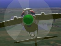
A Frontal view of the Shark Mouth is particularly interesting to me because I have seen a photograph of a modern P-40 from that angle and my version looks VERY close in my opinion. To get that view right requires not just the paint to match but the nose contours have to be pretty close as well.

Regarding the Intake Dividers, I like the way they turned out. This version actually has textured Radiator faces unlike prior versions. The way this was done was VERY expensive from the AF99 resource standpoint.
IIRC, the Radiator Face, Intake Interior Walls, and the Dividers AND the roof of the Shark Mouth area are all in the Body, Main group with the display priorities set so that from Foreground to Background we have

Dividers
Roof
Interior Walls
Radiator Face

They are all Glued at the Radiator Face
The exterior is in both the Body, Main group AND in the Nose Group
If you try out the Aeroplane without texture files, it will become much more apparent what I actually did.

It is actually a touch more complicated, but the basic idea is that if you are behind the CoG, the display order of the interior parts doesn't matter because all will be hidden by the exterior of the cowl.
If you are ahead of the CoG, the interior parts are displayed in proper order and then covered by the duplicated exterior.

This is one of the goofy things about AF99 in that there is no way to specify something as ALWAYS in the background.
AF99 always expects a viewing plane spec to make the determination and will add one if there isn't one.

Regarding "Temperamental" flight characteristics, This beast is tuned to the best of my abilities to match pilots reports. It wasn't always the nicest handling aircraft especially with all the trim changes, but the combination wasn't bad. If you watch airshow displays, P-40 pilots fly a lot more maneuvers (especially vertical maneuvers) than a typical high speed pass that you see with other warbirds.
The very "Pointable" characteristic is just a side effect and I wish I knew how exactly to quantify and reproduce it. Strange thing is that my FW 190A also has this characteristic but even more so (as it should).

- Ivan.
 
Back
Top