Warhawk

Noses and Mouths

Hi Ivan,
Very interesting, thanks, and psychologically effective, no doubt!
Thanks also for the description of your air intake construction.
I´ll investigate in the .air files and look for indications as regards the "Pointable" characteristic. I remember you once asked a rhetoric question on what to do with concentric counter-rotating props.
Cheers,
Aleatorylamp
 
Hello Aleatorylamp,

In one of your earlier replies you commented that rounder is better.... Usually it is, but some things are supposed to be angular instead of curved. I found a P-40 model for another simulator that had probably 10 times the polygons of mine but had enough general shape problems that I believe it is a much inferior model. The author should have looked at more photographs and done a bit more than just making a "Tube" and squishing it into a shape resembling parts of a P-40.

I think it is about time to take this P-40E out for some more test flying and experiments.

- Ivan.
 
Merlin Powered Hawks

Hubbabubba made a very good suggestion a while back that the next P-40 perhaps should be a Merlin powered version.
Since I have what I believe to be a pretty well dimensioned P-40E, the next one might be a Short Tail Merlin P-40F.

The first step with any of these modifications is to do a little research to note what the changes might be.
The most obvious change is the removal of the Carb Scoop, but there are many more changes than that.

This again is where we run into the issue of contradictory data from different sources. If they contradict, which do you trust?

The P-40E that was just completed was built to an overall length of
31.73 Feet or 31 feet 8.75 inches. This does not agree with William Wylam's drawings, but was listed in a couple technical manuals and also in "America's Hundred Thousand" by Francis Dean.

The P-40F Pilots manual lists the
Early P-40F at 31 feet 7 23/32 inches
Late P-40F and all P-40L at 33 feet 3 23/32 inches.
The P-40F Service Manual lists the length of
Early P-40F at 31 feet 7 3/4 inches which is close enough to be considered identical.

So far so good. Multiple sources state that the Extension to the Tail was 20 inches and this is an exact match.

Now comes the fun part:
The P-40N Erection and Maintenance Manual states that the overall length of the P-40N was 33 feet 3.7 inches
Other Long Tail Allison P-40s are also listed as 33 feet 3 23/32 inches or 33 feet 4 inches.

The problem is this:
If the Tail Extension on a Merlin P-40 iw 20 inches, then does it make sense than the Tail Extensions on Allison P-40s is only 19 inches?

Or is the nose section on later P-40s shorter which is not supported by photographs. If anything, the later Allision P-40s had LONGER noses..... Now if the Nose is longer, something else must be shorter, but where?

Hmmm.... Makes you wonder.
- Ivan.
 
Another Minor Correction

.....And just when you thought it was safe, I just found that one of my reference drawings probably had a slight error.
The actual drawing wasn't bad. The annotation on it was incorrect.

The drawing listed the P-40E Thrust line to be 3.75 inches above the FRL
The newer drawing found in looking for data for the P-40F states that it should be 3.078 inch.
The really ironic thing is that this is pretty much the difference between the current model and the prior model so I am putting things back the way they were before.... Sheesh!

The change would not really be visible (about 0.06 foot difference) but I have to do it anyway for the P-40F.....
Corrections in the quest for perfection. It never ends....

- Ivan.
 
Drawings and sketches

Hi Ivan,
Yes, it is annoying when one´s annotations on a blueprint have a glitch, but small ones often go unnoticed on the visual model.
What causes more of a problem though, and that´s when you have to "eyeball" it, is when factory blueprints are not available. I have often found the drawings and sketches available for any given model to have some differences, not only depending on the author if there are several sketches available, but differences with photos of the planes.
These differences, can mostly only be corrected by comparing the photos with screenshots of the model - if you get angles and distances right. I have sometimes had to correct rudder height, nose or chin curves, and even elevator widths and lengths this way. Of course by how far the result is accurate with reality is impossible to tell and it is only the general impression I can go by.
But I can understand your strive to get it perfect! I get similar sensations when I am building something!
The best of luck!
Cheers,
Aleatorylamp
 
Dimensional Change

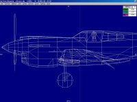
In looking over the Drawings and the mismatch, what I see now is that the actual change to make a correction to the Thrust Line from 3.75 inch above the FRL to 3.078 inch above the FRL is actually only 0.04 feet.
It is a little less because of the rounding errors necessary to represent items listed in Thousandths of an Inch to the AF99 resolution which is only 0.01 Foot or 0.12 Inch.

The next step is to actually make the correction and fix everything else this will break.
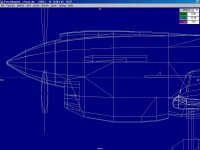
It doesn't look like much of a change in the screenshot, does it?
I am almost tempted not to do it except my eyeball has been telling me since I built this version that the nose was a touch too high.

The quest for "Perfect" dimensions never ends!
- Ivan.
 

Attachments

  • Minus04.jpg
    Minus04.jpg
    60.8 KB · Views: 0
minimal

Hi Ivan,
Usually the pixels on the drawings that I have to work on for old models are thicker than the differences in your blueprint! Quite honestly, if my humble opinion serves, such small differences for me would qualify as negligible, and I really woudn´t worry.
Cheers,
Aleatorylamp
 
Dimensions

Hello Aleatorylamp,

I know the feeling of working with very imprecise drawings.
That is how my first models started and even more recently, some of the models were created from much less than perfect drawings.
The issue here is that I KNOW the correct dimension here and this discrepancy is the largest one that I know about thus far.
The Carb Scoop that I most recently worked on was a result of this. I could not get the shape right with trying to keep a smooth curve and keeping within the dimensions and now I know WHY I had that issue.

Not knowing is a good excuse, but here I DO know. It also appears that ALL of the P-40s had the same Thrust Line so correcting it once here corrects it for all the descendants as well. It may take a while to get there though....

- Ivan.
 
Moving the Engine

This screenshot shows a slightly revised Template for the new Parts locations and moving some of the actual pieces of the aeroplane.
Shifting the Thrust Line down 0.05 feet appears to be the best solution.

There are four basic areas to address:
1. The Carburetor Scoop (Probably the best reason to shift so many Parts)
2. The Contour Line of the entire Fuselage back past the Cockpit to ensure there are no strange bends
3. The actual Cowl Panels.
4. The Radiator Intake and pieces on the lower side of the Cowl.

This looks quite tedious, but hopefully this will not take too long.

- Ivan.
 

Attachments

  • EngineMove1.jpg
    EngineMove1.jpg
    61.9 KB · Views: 0
a worthwhile effort!

Hi Ivan,
An aircraft with such an appealing design as this one is definitely worth the effort to get as exact as possible if within the capability of the modeller and the limits of his patience!
Cheers,
Aleatorylamp
 
Comparison to Factory Drawing

Hello Aleatorylamp,

I don't really know if it is worthwhile, but it is what I am doing. I need a break from the Gauge Project because I am pretty much stuck. I have changed the code to what I understand it needs to be and yet I am not getting the results I want. I will continue at some point, but several days of zero results tells me I should change subjects.

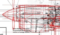
Here is a comparison of the revised nose with a set of factory drawings.
The match isn't too bad at this point but there are a couple changes that are pretty obvious.

1. The Cowling Flaps are way too short in my model
2. The contour of the Carb Scoop is quite a bit off. Mine has too much of an arch.
The opening on mine agrees better with photographs than the factory drawing does though.
3. The Front of the Radiator needs to be significantly deeper.
4. The Rear of the Radiator has a gradual sweep upward that my model does not.

There are many more small mismatches, but the major components line up pretty well with the rest of the drawing.
A very interesting issue here is that my model lines up much better with these drawings han they do with photographs of actual aeroplanes! It also looks much better in the simulator than here in these screenshots.

- Ivan.
 

Attachments

  • FactoryCowlDrawing.jpg
    FactoryCowlDrawing.jpg
    123.6 KB · Views: 0
Of factory drawings and photos

Hello Ivan,

There is something that I have recently been asking myself when it comes to factory drawings and actual photos of planes: To what extent could changes be introduced into a given production batch, differing from the factory drawings of the initial design? These changes would perhaps only have drawings, if any, reflected on supplementary subsections to the main ones.

With the different photos available of any given model I sometimes have the uncanny sensation that I am being tricked by optical illusions, ...or are the small differences from one unit to another in effect real?

Moreover, to what degree would a factory engineer be capable of simply adjusting certain panels on a specific unit, to fit over some alternative part being fitted that was different just because of a logistics problem, especially in the wartime production rhythm?

So then, what are we doing as virtual modellers? Producing models as per factory specification drawings, or producing the planes that actually flew? ... or are we just splitting hairs?

I would muse that it is something in-between: We can apply our own "magic", to use your expression, so that suddenly, Presto!: Our models fit both concepts!

Cheers,
Aleatorylamp
 
My goal as usual is to produce "My Own Impression" of the aeroplane in question.
When possible, use all resources available but NOTHING is infallible other than a photograph but those are subject to a lot of factors and to interpretation.

My latest issue is that I am hitting a place where the drawing and a couple specified dimensions do not match. Which should I believe? I am also getting small inconsistencies depending on where I get the wire frame image from. The one from DPED and the one from AF99 seem to differ slightly in proportions.

Again, it will be a best judgment thing. Flight models have always been a best judgment thing for me.

- van.
 
Blueprints

Hi Ivan,
I´ve just checked the difference you mentioned in the Dped and AF99 blueprints, and I was quite shocked when I saw the magnitude of this difference!
Just to show, I made a comparative joint screenshot, and compared it to Paul Matt´s drawings. It appears that the AF99 blueprint is quite a bit too long, and that the Dped one matches the drawings. I hate to think about what connotations this could have in all these years...
Good luck!
Aleatorylamp
 
more on blueprints

Hi Ivan,
I just thought I´d investigate the Aircraft Animator blueprint too, and it turns out that dimensions coincide 100% with Dped blueprints and Paul Matt´s drawings in the case of the AT-9.
Cheers,
Aleatorylamp
 
Hello Aleatorylamp,

So you also see the differences between AF99 and DPED....
....and you can confirm that AA agrees with DPED.

Now the next trick is to figure out which is the most correct and if the difference is constant or distorted.
I have a couple ideas as to how to do that, but until then, the Warhawk is on hold because I suspect I may be making unnecessary corrections.

- IIvan.
 
Distortions

Hi Ivan,
I remember that the reason I´d almost given up on the AT-9 before resuming construction was that suddenly the height started to go off somehow. Now I realize that it was when I was adjusting the AF99 wireframe to side-view photo. As the wireframe was too long, the adjustment reduced the height - it was driving me crazy.
My first impression is that both the Dped and the AA wireframes are trustworthy, but I´ll have to make some more exact measurements.
I´ll keep you posted!
Cheers,
Aleatorylamp
 
Distorted Wire Frames

Hello All....

Here is a little comparison between Wire Frame Models in
Aircraft Factory 99
Aircraft Animator
and
DPED.

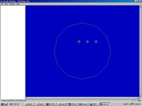
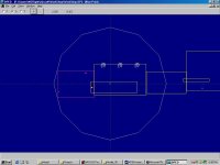
The model here is very simple. I just took one of the Workshop Projects I had and added a 12-sided Circle imported Part.
A screenshot of the saved Assembly in AF99 was then taken.
After producing the project, I then took a screenshot from AA and from DPED.
The results were interesting....

DPED
Height = 127 to 651 = 524 Pixels
Width = 250 to 774 = 524 Pixels

AA
Height = 165 to 574 = 409 Pixels
Width = 389 to 798 = 409 Pixels

So far, so good.....

AF99
Height = 111 to 695 = 584 Pixels
Width = 205 to 819 = 614 Pixels

Hey! The numbers don't match!!!
So the stretching is obviously not imagined.
There actually is just over a 5% difference.

Next step is to figure out if this can be fixed.

- Ivan.
 

Attachments

  • Circle_AF99.jpg
    Circle_AF99.jpg
    26.1 KB · Views: 0
  • Circle_AA.jpg
    Circle_AA.jpg
    34.3 KB · Views: 0
  • Circle_DPED.jpg
    Circle_DPED.jpg
    41 KB · Views: 0
Scaled Correctly

So, now that we know which screenshot NOT to use, how does the Warhawk compare to the drawings?

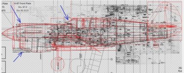
The attached screenshot shows an overlay.
I believe it is pretty close but there are still a couple issues as noted by the arrows.
The worst section is on the Radiator scoop as expected.
The Carburetor scoop needs its contours adjusted a bit.
The Windscreen should also be moved back slightly. I believe the difference is under one inch.

- Ivan.
 

Attachments

  • P-40E_Differences.jpg
    P-40E_Differences.jpg
    82.8 KB · Views: 0
Reliable shapes

Hi Ivan,

It is interesting that the AF99 wireframe distortion now has been nailed down to a definite dimension in pixels!!

At least using DPed or AA´s wireframes allows reliable, undistorted shapes, and is a relief for trustworthy adjustments after comparisons to drawings or convenient photos. With the latter, of course, there is also the added factor of distortion which you have mentioned too, due to excessive camera proximity, and the best photos I suppose would be those taken with tele-objective from a certain distance.

I certainly miss some kind of intelligent image recognition program for airplanes, similar to those available for face-recognition in virtual photo albums, which would allow a rotation to create a 3-view set in the X, Y, Z axes! ...Wishfull thinking.

Cheers,
Aleatorylamp
 
Back
Top