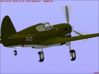
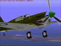
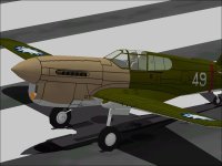
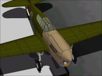
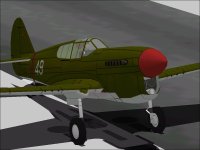
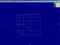
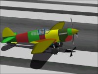
Warhawk

Merlin Power

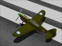
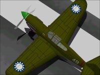
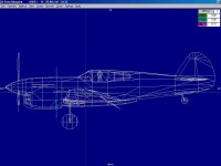
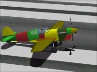
Now that I have a pretty reasonable P-40E as a starting point, the Conversion / Duplication Process for the Merlin powered P-40F begins.
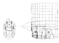
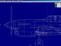
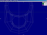
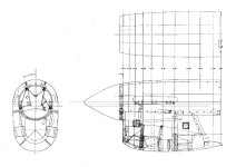
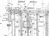
This model will be a bit more difficult because the scans of the Factory Drawings for the F-model Cowl section is much worse quality and appears to have some distortions.

There are also some disagreements in dimensions between the various models:
The P-40E as modeled is 31 feet 8.75 inch or 31.73 feet in AF99 units.

The length varies a bit depending on the source. The most plausible dimensions are 31 feet 8 inch to 31 feet 9 inch with 31 feet 8.75 inch being the most likely value in my opinion.

The length of the P-40F also has a similar variation ranging from 31 feet 7 9/16 inch to 31 feet 7.75 inch depending on the aircraft manual. The variation is actually much higher than this from sources other than the manuals.

The Datum Point as stated earlier is at Station 1 (The Firewall) longitudinally and at the Fuselage Reference Line vertically.
The Forward End of the Cowl is 87.0 inches ahead of the Datum for most Hawk 87 models.
For the Hawk 87D (Merlin Powered) P-40F / P-40L, the End of the Cowl is only 85.75 inches ahead of the Datum.

The Merlin was a heavier engine than the Allison and I believe the difference in engine location was to maintain a consistent CoG without having to add ballast.

Another feature worthy of note is that the forward edge of the Cowl had a slight bevel and the Spinner actually overlapped the Cowl slightly. The visible gap that is in my model is really just a line on the real aeroplane.

When I scaled the Factory Drawing of the F-model Cowl to match the 85.75 inch (7.1458 or 7.15 feet) dimension, I found that the top of the Cowl did not quite match the other drawings and the length of the Spinner was about 1/2 inch too short as compared to the E-model Spinner.

Now comes the fun part of measuring offsets for the new 3D model.
(The CoG of the model remains at 2.35 feet Aft and 0.55 feet Below the Aircraft Datum Point.)

- Ivan.
 

Attachments

  • F-CowlUpload.jpg
    F-CowlUpload.jpg
    63.1 KB · Views: 0
Hi Ivan,
Sounds great, and I´m glad you sorted that out. It´s amazing how many details one can unearth during an in-depth investigation. It makes modelling all the more interesting!
Cheers,
Aleatorylamp
 
Hello Aleatorylamp,

I don't know that I really have sorted anything out yet.
I suspect the mismatches will become more obvious as I build further
The length discrepancy is between 1/16 inch and 1/2 inch depending on the sources.
Unfortunately I don't happen to have a P-40F that I can go measure.
I also would not have a method of measuring such a large object so precisely anyway.

- Ivan.
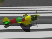
 
The most obvious difference between the P-40E and P-40F is the lack of a Carburetor Scoop on the F model.
The Allison used a down-draft Carburetor which is why the airflow had to come from the top.
The Merlin on the other hand used an up-draft Carburetor which is why its airflow came from the bottom.

The first and most obvious step was to remove the Carburetor Scoop.
This served two purposes.
The primary purpose was to get some instant gratification and see something closer to the final version.
The secondary and more important purpose was to free up two Components and about 50 Parts to use in new construction.
It is pretty obvious already that the Merlin Warhawk will be less complicated and probably also less resource intensive.

Note that there is a dark spot on the upper rear of the Cowl. This was there to provide a shading difference between the Cowl and Carburetor Scoop on the earlier aeroplane.
It is easily removed.
There are certain to be other less simple texturing differences.

The second step which I only partially completed last night was to move the Nose Pieces 0.10 feet Aft.
In reality, the difference should be 1.25 inch which is really 0.104-something feet so the Cowl Pieces were only moved 1.200 inches Aft. The Propeller, Spinner and associated Glue Parts also need to be moved.
This granularity in AF99 dimensions also serves to hide the 1/16 inch discrepancy I was unable to resolve.

Here are a couple screenshots of the current status. The Spinner to Cowl Gap is 1.32 inches here. I plan to leave it at 0.12 inch when completed.

- Ivan.
 

Attachments

  • F-MinusScoop.jpg
    F-MinusScoop.jpg
    51.8 KB · Views: 0
  • F-NewUpperCowl.jpg
    F-NewUpperCowl.jpg
    56.2 KB · Views: 0
Here are a few screenshots from last night.
The Radiator Housing area of the Merlin Warhawk are very different.
The Radiator Inlet is much narrower and also much deeper.
The entire Radiator Housing is also much shorter

The division line between the "Forward Fuselage" and "Cowl" sections is right at the Radiator Exhaust and that will need to be moved forward.
The Warhawk lost two Components for the Carburetor Scoop, but will likely use them up with the new Cowl Fairing on the underside of the Fuselage.

The Steps for the entire Conversion were the following:
1. Remove the Carburetor Scoop and adjust panels to close the upper Cowl area. - Completed
2. Move the Spinner / Propeller / Cowl pieces to shorten by 1.25 inches. - Completed
3. Re Shape the Cowl / Radiator Housing - Working
4. Add a Bulkhead at +4.35 feet to be the new dividing line - Working
5. Replace Cowl Interior pieces - Waiting
6. Redesign the Radiator Exhaust - Waiting
7. Modify Textures to fit new pieces - Exact Tasks Unknown so far

- Ivan.
 

Attachments

  • F-NewBulkhead.jpg
    F-NewBulkhead.jpg
    51.1 KB · Views: 0
  • F-NewShape.jpg
    F-NewShape.jpg
    63.9 KB · Views: 0
  • F-RadiatorInlet.jpg
    F-RadiatorInlet.jpg
    51.8 KB · Views: 0
The Steps for the entire Conversion were the following:
1. Remove the Carburetor Scoop and adjust panels to close the upper Cowl area. - Completed
2. Move the Spinner / Propeller / Cowl pieces to shorten by 1.25 inches. - Completed
3. Re Shape the Cowl / Radiator Housing - Completed
4. Add a Bulkhead at +4.35 feet to be the new dividing line - Completed
5. Replace Cowl Interior pieces - Working
6. Redesign the Radiator Exhaust - Working
7. Modify Textures to fit new pieces - Exact Tasks Unknown but looks worse than I thought it would.

My first try at a Carburetor Intake Duct wasn't too bad as a structure but I found that there is actually a slight tilt to the opening which means it cannot match up very well with a Structure.
Another issue is that the Carb Ducting is not the same height from front to rear and this really causes a shape problem when represented by a Structure.

The Radiator Exhaust area required a LOT of reworking on the Lower Fuselage / Cowl Fairing area.
This has been the most difficult part thus far, but it was finished a couple nights ago.
Note that the Cowl / Radiator Housing is MUCH shorter. The area formerly occupied by Cowl Flaps has been almost entirely removed and the Cowl Flaps will be moved forward.
The Cowl looks a bit strange at the moment because very few of the Textured Panel Lines actually match up to reality.
In fact the Texture needs to be shifted up a bit because it extends all the way to edge of the file.
(I like to have a 1 Pixel border around all the Textures.)
Luckily there is no longer a Carb Scoop over the Cowl, so there is room to shift things a bit upward.

This shifting of Textures brings up a problem which I didn't know enough to address very early on.
The entire Fuselage is textured to a scale of 256 Pixels == 11.6 feet.
Although I can shift from 1 to 12 pixels, there is no amount I can shift the texture that does not cause a different mapping onto the pieces of the aeroplane.

- Ivan.
 

Attachments

  • F-CarbIntake.jpg
    F-CarbIntake.jpg
    54.7 KB · Views: 0
  • F-CowlFairing.jpg
    F-CowlFairing.jpg
    45.3 KB · Views: 0
  • F-CowlFlaps.jpg
    F-CowlFlaps.jpg
    59.4 KB · Views: 0
  • F-CurrentProfile.jpg
    F-CurrentProfile.jpg
    54.5 KB · Views: 0
Hello Ivan,

Very interesting, the description of what you are doing. I´m taking a few notes for myself along the way.

Modifications always catch me out. Initially one doesn´t expect complications: "Oh, nothing! - piece of cake!", It NEVER is! Modifications invariably branch out, affecting a cascade of other parts, and it ALWAYS gets far more complicated.

Now that I´ve got everything lined up on the Orion, the only ("only" - good grief!) job left is a thicker wing. BUT, now the three wing sections won´t fit the engine-nacelle structures so well. The nacelle walls now sometimes take display priority over the upper and lower wing surfaces. If I can´t get that out with some decent glue, I´ll have to try out radically different strategies. It´s always back to square one, isn´t it?, but one gets there eventually.

It´s also interesting how textures affect surfaces. They can either enhance a bulge, or create a physically inexistent one, or completely disguise one! Truly amazing.

Cheers,
Aleatorylamp
 
Hello Aleatorylamp,

Actually this Merlin modification is much less complicated and labour intensive than the last two major rebuilds:
(The Wylam Drawings to Current Drawings and Thrust Line from 3.75 inch to 3.078 inch.)

I actually haven't documented as many of the changes here as I have done in the past. I don't think there is actually much of an audience. Notice how far apart the posts are spaced? Sometimes there really isn't anything going on and sometimes there is a lot.

Regarding Orion, I would have taken a different approach to the aeroplane.
I still think the best (or least painful) approach would have been to build each engine as two Components and the Wing as a single Component.

You might have noticed that I don't tend to take up other designs and modify them.
I believe the payoff is much less and the frustration level is probably about equal to that of a new design.
The end result is also my aeroplane rather than someone else's.
I have a pretty predictable system to naming and it helps me find things faster on my own projects.

- Ivan.
 
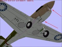
These two screenshots show what I call the Intake Fairing added to the underside of the Fuselage.
I WOULD have taken another screenshot from further aft, but my computer locked up and I didn't care to wait for it to reboot and go through the File System Checks.

- Ivan.
 

Attachments

  • F-IntakeFairing1.jpg
    F-IntakeFairing1.jpg
    56.4 KB · Views: 0
  • F-IntakeFairing2.jpg
    F-IntakeFairing2.jpg
    56.1 KB · Views: 0
After an hour or so of editing, I saw this result right after I textured the Intake Fairing.
I suspected the issue was not an AF99 error and I had also been experiencing some strange issues, so I rebooted the computer.
These issues went away with the next build.

The computer is definitely misbehaving a bit.
- Ivan.
 

Attachments

  • F-PuncturedTyres.jpg
    F-PuncturedTyres.jpg
    44.4 KB · Views: 0
  • F-BrokenCowl.jpg
    F-BrokenCowl.jpg
    60.6 KB · Views: 0
Bugs and

Hi Ivan,

Thanks for the suggestion on the Orion Wing issue. I´ll address that further on the other thread.

As regards texture issures, missing bulkheads, or sometimes missing insignia intakes, when CFS1 starts up and loads a plane initially, I find it often gets fixed by simply re-loading the plane, and won´t go away by re-starting the computer, but perhaps it´s not the same bug that you are experiencing.

Talking about bugs: A few months back my AF99 started giving an error message every time I compile a plane, saying that the model is currently loaded into the simulator - and CFS1 isn´t even running! So I just ignore it, re-click the compiling button, and it proceeds correctly!

Yes, I suppose the audience for FS98 and CFS1 is rather limited nowadays, and any new people go directly for the new flight simulators and aeroplane building programmes, but I just can´t get myself to like Gmax or Fsds - although I have tried several times each. If CFS2/3, FS2004 and FSX at least had kept up the backwards-compatibility with the old style Autocad files of AF99, it may have been a different matter. Apparently it would not have hampered anything, and the incompatibility was totally intentional after FS2002. If FS2002 could handle both new and old model files, why not the subsequent ones? Too bad...

Cheers,
Aleatorylamp
 
New Cowl Dimensions

....And just when you thought it was safe....

From the first drawing of the entire Cowl, the length from the Datum to the forward end of the Cowl appeared to be 85.75 inch.

In looking over some of the other drawings, it appears that my interpretation of the earlier drawing was incorrect.
The number really should be 86.75 inch as can be seen in the detail on the lower Cowl drawing.

It appears that a few pieces will get shifted around a bit yet again.
Luckily there appears to be no significant difference with either the Cowl Opening or line of the Upper Cowl.
Time for another rework....

- Ivan.
 

Attachments

  • F-CowlUpload.jpg
    F-CowlUpload.jpg
    63.1 KB · Views: 0
  • NewCowlDimensions.jpg
    NewCowlDimensions.jpg
    135.5 KB · Views: 0
In re-shaping the nose of the Merlin Warhawk, I reached the point where the 3D Model extended past the edge of the texture file.
That meant that the mapping of the texture file would have to be changed.

The Warhawk uses a scale of 11.60 feet per 256 Pixels.
The mapping of the texture was right up to the edge of the file.
It needed to be moved at least 2-3 pixels to leave a slight margin to the edge.
There was enough room to move it up to 13 Pixels before the opposite edge was hit.

I wanted the alignment of the panel lines to be EXACTLY the same between the Merlin and the Allison versions.
The problem is that with a scale of 11.60 feet per Pixel, there is no shift between 2 and 13 Pixels that would produce the same alignment.
The end result is that it is not quite an exact match but fairly close.

As can be seen from the screenshots, some parts of the Cowl still need to be adjusted and obviously the Carburetor Inlet still needs a texture. The texture for the Cowl Flaps at the bottom is not ideal, but is probably as good as it will get at this scale of texturing.

At this point, the panel lines are a pretty fair match to my references for a P-40F.

The folks in the paint shop chose a very light coloured primer to make the panel lines more distinct at this stage.

- Ivan.
 

Attachments

  • F-CowlPanelLines1.jpg
    F-CowlPanelLines1.jpg
    56.4 KB · Views: 0
  • F-CowlPanelLines2.jpg
    F-CowlPanelLines2.jpg
    50.6 KB · Views: 0
  • F-CowlPanelLines3.jpg
    F-CowlPanelLines3.jpg
    62.5 KB · Views: 0
Carburetor Inlet

A few things were moved around last night and the holes in the Cowl got fixed.
The Carburetor Opening appears to have a Choke or diverter of some kind that tends to be closed for Take-Off or Landing but appears to normally be open in flight.

Plenty more to do before it is finished.

- Ivan.
 

Attachments

  • F-CarbInletClosed.jpg
    F-CarbInletClosed.jpg
    48.4 KB · Views: 0
  • F-CarbInletOpem.jpg
    F-CarbInletOpem.jpg
    43.1 KB · Views: 0
Looks very intriguing...
I was already wondering what it was. It´s a cool detail on the model.
What I like about it is how it fits behind the cowl walls without bleedthroughs. You´d already explained how that was done with the "Y" separators in the cowl on the other model.
Cheers,
Aleatorylamp
 
Bleeds

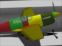
Here is the latest on the Merlin Warhawk from a couple days ago:

The Radiator Exhaust area took a few tries but is finally shaped about the way I wanted.
It isn't completely faithful to the original because of AF99 resource and assembly limitations.
To look correct, the textures need a lot of adjustments.
Although the general appearance looks not very different from the Allison birds, there actually have been a lot of pieces reshaped here.

Along the way, I was looking over the rest of the changes and noticed..... A BLEED!!!!
Hopefully this will not be difficult to eliminate and also will not burn up many more Parts.
I suspect it is a consequence of my shifting of various pieces back and forth and forgetting to shift the Glue Parts at the same time.

We shall see.

- Ivan.
 

Attachments

  • F-CowlBleed.jpg
    F-CowlBleed.jpg
    53.4 KB · Views: 0
  • F-RadiatorExhaust.jpg
    F-RadiatorExhaust.jpg
    80.6 KB · Views: 0
A little bleed is like a fly you try to swat,
but just manages to get away, aided by
the air pressure from the fly swatter...

Cheers,
Aleatoryplamp
 
This Bleed is actually not hard to fix and I already know where it came from.
It will just cost about 10-12 more Parts to the model.

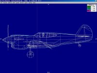
The original P-40E was designed with its Frames located where major contour changes occurred on the Fuselage.
This can be seen in the first screenshot.
Note that the second Frame from the Spinner coincides with the Radiator Opening.
This was chosen so that it would work as a Glue position to separate pieces behind from pieces in front.

With the modifications from the original design (Wylam Drawings) to the better Fuselage Station diagram the Radiator Opening was moved Forward a little bit. The Intake Walls were also moved forward at the same time of course.
I chose not to move the Frame location forward on the upper Cowl area because I did not want to rebuild the Cowl.
I did not see any bleeds resulting from that change...... But there WERE some.
They just were not as visible because the move of the Radiator Opening was very slight and the angle for the bleed was very small.

The Merlin P-40 required an additional forward move of the Radiator Opening and with this move, the angle became greater, thus I was able to see it better with this version of the model.

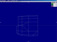
The two additional screenshots show the views from ahead and behind the CoG plane.
The fix is actually fairly easy.
The first row of Cowl Parts just needs to be added to the main Cowl (Dark Olive) which will cost between 10 and 12 more Parts depending on how I choose to do it.

I should probably go back and edit the P-40E for the same change.

- Ivan.
 

Attachments

  • BluePrintOld.jpg
    BluePrintOld.jpg
    52 KB · Views: 0
  • F-AheadCG.jpg
    F-AheadCG.jpg
    48.5 KB · Views: 0
  • F-BehindCG.jpg
    F-BehindCG.jpg
    40.4 KB · Views: 0
  • Evolution.jpg
    Evolution.jpg
    53.2 KB · Views: 0
The small Cowl bleed was fixed this morning.
The CowlMain Component now has 12 more Parts than it did before.
The view from Forward of the CoG is unchanged.
The additional Parts in CowlMain should block the bleeds from Aft of the CoG.
The contrasting colours made this little problem very easy to find and give an idea of the actual assembly sequence for this project.

Parts Count is now 1109.

- Ivan
 

Attachments

  • F-CowlMainOld.jpg
    F-CowlMainOld.jpg
    27.5 KB · Views: 0
  • F-CowlMainNew.jpg
    F-CowlMainNew.jpg
    28.6 KB · Views: 0
  • F-AheadCG.jpg
    F-AheadCG.jpg
    48.5 KB · Views: 0
  • F-BehindCGRevised.jpg
    F-BehindCGRevised.jpg
    46.4 KB · Views: 0
Hello Ivan,
Looks good! Parts count is not giving a nightmare either.
I´m going to adopt your way of using provisional coloured un-textured sections to discover bleedthroughs!
So then, forward cowl ring parts are now duplicated into the main cowl component (body-Main?), and the first cowl ring, is that grouped in Nose then, with spinner and prop?
Cheers,
Aleatorylamp
 
Back
Top