-
There seems to be an uptick in Political comments in recent months. Those of us who are long time members of the site know that Political and Religious content has been banned for years. Nothing has changed. Please leave all political and religious comments out of the forums.
If you recently joined the forums you were not presented with this restriction in the terms of service. This was due to a conversion error when we went from vBulletin to Xenforo. We have updated our terms of service to reflect these corrections.
Please note any post refering to a politician will be considered political even if it is intended to be humor. Our experience is these topics have a way of dividing the forums and causing deep resentment among members. It is a poison to the community. We appreciate compliance with the rules.
The Staff of SOH
-
Please see the most recent updates in the "Where did the .com name go?" thread. Posts number 16 and 17.
You should upgrade or use an alternative browser.
Warhawk
- Thread starter Ivan
- Start date
aleatorylamp
Charter Member
Very good this 3rd. texture of yours with the Pegasus detail - Definitely upload that one!
If one were forced to choose between the other two, it would be very difficult, because both have their advantages: Well done camo versions always look striking, and are rarer on models than plain coloured ones for their texturing difficulty. Dark, plain-coloured versions I feel have a no-nonsense atmosphere to them which is also appealing.
I know what I would do (all 3!), but it´s your creation... So, as Smilo says... it´s your call!
Cheers,
Aleatorylamp
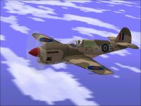
Glad you approve. I am also a bit surprised at how nice the Merlin version looks.
Although I had not planned it that way, it still appears to be quite agile and performance appears to be very good.
Thanks also, Aleatorylamp,
The plan was actually to do something pretty similar to what I did earlier with the Hawk 81s.
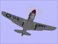
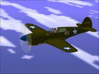
There were two uploads even though they were basically the same project; One would have the Green US Army paint scheme set up as default and the other would have the RAF Desert paint scheme as default. Both would have all three textures included.
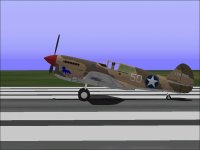
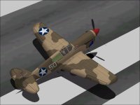
I don't think the USAAF Desert scheme looks too bad either.
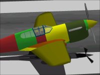
Note that the US Army Desert paint scheme had a LOT of variations with some seriously strange combinations such as Pink overall.
I was also debating on doing a CheckerTail, Shark Mouth 112 Squadron, or Monochrome Tan as was originally used.
There are also at least two Camouflage patterns used in the desert.
For now, I am staying generic.
- Ivan.
Attachments
I just finished uploading the Merlin Warhawk that you suggested back in Post #31 a while back.
Hopefully this meets your expectations.
It is certainly a bit more than just leaving the Carburetor Scoop off a regular Allison P-40.
My technicians are waiting for the upload to be approved before sweeping up the metal scraps from the workshop.
Although I like the RAF paint scheme, the reality is that very few P-40Fs actually served with the RAF.
Some were also used by the French and sent to Russia of all places.
- Ivan.
Attachments
aleatorylamp
Charter Member
I´ve just downloaded and tried out your new plane!
Definitely a very beautiful job, and exciting and precise to fly.
Very nice!
Thanks!
Cheers,
Aleatorylamp
I like the result of this project also.
It still has the nice handling of the prior versions of the Warhawk despite the extra 300 pounds of weight.
The climb rate is actually a bit higher than the Allison versions in my models, but that isn't proof of anything since my flight modelling is not necessarily accurate.
The odd thing that I believe I found is that down low, the Merlin Warhawk was a bit slower than a contemporary Allison even though the Merlin would have more power. Perhaps it is because of restrictions on power settings, but to create this effect, I had to turn up the Drag Coefficient quite a bit. This would imply that the bigger radiator scoop caused a LOT more drag.
So now the Workshop is officially clear. I think the technicians are actually working on tools to make the next project easier.
- Ivan.
aleatorylamp
Charter Member
Given the limitations in the .air file for the two different turbo superchargers for the Allison and Merlin engines, it´s most probably as good as it gets.
Currently, and for a totally different era and performance envelope, I´m tweaking the two different Benz Bz.III (165 hp) and Bz.IV (230 hp) engines performances on the Albatros G.II and G.III (1916 and 1917) that I want to upload as soon as possible, to clear my own workshop and see what´s on otherwise.
Cheers,
Aleatorylamp
Yes, As far as I know, there are limitations on SUPERchargers are handled in CFS.
Neither the Allison nor the Merlin as installed in the P-40s ever had a TURBOcharger.
The Allison installation in the P-38 Lightning did have a Turbocharger and differences in plumbing are pretty serious.
Next step in the evolutionary process of my P-40s is going to be a revisit of the P-40E Warhawk to correct the not so obvious bleed problem in the Cowl area and to remap a couple textures that might be located less than optimally.
The underside behind the Cowl also needs an examination for faults as I found in the Merlin Warhawk.
I don't know for sure that there are any that were not caused by the numerous changes for the Merlin installation though.
It seems almost a shame to chop up such a nice looking Warhawk to correct a few things that are barely visible under a directed examination, but that is what I need to do to have a solid basis for any follow-ons because any errors will be propagated forward.
What I hate the most about this is the need to go through the SCASM adjustment process again.
On the next release, the P-40E will also have a RAF Desert texture available because with just a minor exception, just about everything maps the same between the P-40E and P-40F.
- Ivan.
aleatorylamp
Charter Member
Sorry, yes... I meant just superchargers - the word "turbo" keeps slipping in as in my mind SUPERchargers ARE a kind of turbine, with vanes like a pump, or helicoidal or whatever, even though they aren´t driven by an exhaust-turbo, but by a belt or gears...
...I MUST get into the habit of calling things correctly!
Re: Re-visiting models: I was just thinking... I find re-visiting a model for alterations or upgrading after some years does indeed have its nice aspects. With the familiarity on one hand, and the added experience on the other, with perhaps additional data available, the result is usually quite successful and often includes the satisfaction of improvements or corrections that weren´t planned or expected.
Cheers,
Aleatorylamp
I do think this one turned out looking pretty nice with the Desert Camouflage.
I believe this is this (surprisingly) is the first actual Merlin Warhawk that is more than just the Allison version with the Carburetor Intake removed.
Hello Aleaorylamp,
A Supercharger is just a pump installed before the intake system. Some are turbine driven thus Turbo Supercharger (or Turbocharger for short).
The actual pump on these aero engines is an Impeller (Centrifugal) or kind of a reverse turbine, but there are many forms of supercharger. Impellers are not positive displacement but there are many such as the Roots type that are positive displacement and work regardless of input shaft speed. Spiral Superchargers I believe are also positive displacement.
Positive Displacement Superchargers have the advantage that their output is linear with input shaft speed AND also that there is typically no Lag when the throttle is applied.
Turbo Superchargers may have a delay between Throttle opening and power increase which is referred to as "Turbo Lag" and happens because it may take some time for the (possibly heavy) turbine to come up to speed to supply extra air.
Revisiting older projects is sometimes fun and sometimes discouraging for me. My build standards and practices are evolving with every project and some of the very old ones need so much tedious work that I am hesitant to do any modifications.
As you stated, the nice thing about reworking our own models is that the naming schemes are fairly predictable and things are not hard to find and if they were built once before, there was probably a reason for doing it at the time.
At the moment, models being considered for rework / completion are the SBD Dauntless, FW 190A, Spitfire IX, Ki 61-I, La-5FN, Thunderbolts and of course the Corsairs. All have some aspect that I don't feel like dealing with. The P-40E needs to be updated before any of the others though because it is likely to be the pattern for further development into a Long Tail model.
I don't believe I have ever seen a Long Tail P-40 for Combat Flight Simulator other than my K model and that one has shape problems inherited from the Wylam drawings.
- Ivan.
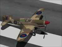
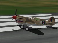
Here are a couple screenshots of the P-40E wearing a RAF Desert paint scheme.
The textures are not quite a direct replacement, especially around the Cowl area (of course) but were not difficult to create.
Note also that the Radiator scoop extends barely past where the original line was.
That is why the bleed at the Cowl was only really visible when the Radiator opening was extended forward on the Merlin version.
There are a couple different ways to correct the bleed (which I can't see but know is there):
1. Move one frame the top of the Cowl slightly forward to match the cowl opening.
2. Extend the Main Cowl Component to include the next row of polygons as was done on the Merlin.
This would cost a bit more than on the Merlin because it is likely the Carb Scoop would also need extended forward.
Best I get to work on it soon.
- Ivan.
Note the difference between the E and F Radiator openings.
It turned out that the changes to the P-40E actually needed 20 extra Parts.
The P-40F only needed 12 Parts but the top Part of the first cowl ring is split into two pieces to allow for the Carb Scoop on the P-40E to make it 14 Parts.
The Carb Scoop also needed to be extended forward which cost another 6 Parts.
Total Parts Count is now 1143 for the P-40E as versus 1111 for the P-40F.
Hopefully there is still enough room for further changes for later P-40s.
- Ivan.
Attachments
aleatorylamp
Charter Member
Interesting, the intricate details. They make each model quite unique.
Cheers,
Aleatorylamp
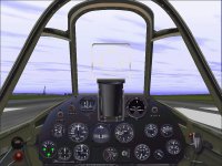
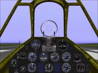
Here is a screenshot of a panel on a very nice repaint of my Warhawk.
The artist's name escapes me at the moment.
Heck, I wish I knew enough to do what he does on these paint jobs.
My version is also included for comparison.
His gunsight is more correct.
My fuel selector is more functional.
- Ivan.
Attachments
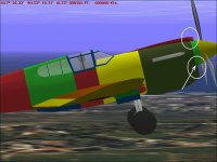
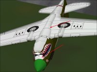
The Cowl Fairing had a non-planar polygon that put a weird dent in the underside.
I fixed it in the Merlin version but had not made the same changes in the Allison version.
There is also a slight line in the underside of the Cowl by the intake that looked like a mapping problem but didn't go away wen I remapped this area. I still don't know what it is, but the problem looks small enough I will just leave it for now.
The SCASM process was done very late last night. The really amazing thing is that most of the changes to the SCASM SCX source when copied from the prior version actually compiled without error. Even with 20 extra polygons, most of the SCASM code didn't change.
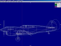
The second screenshot shows the outline of the previous P-40K model and shows why I am just going to start over from the P-40E. This picture only shows the profile. A plan view would show even more issues.
- Ivan.
Attachments
The Curtiss P-40 is the subject of a great amount of literature and documentation.
There are many surviving examples in museums and there are even many flyable examples.
With this being the case, one has to wonder why there are so much conflicting data.
Is it because there were that many variations in the actual aircraft or just that inaccurate numbers were recorded and propagated forward? Is it because of rounding errors?
From what I have been able to gather, the Wing Span of the P-40 series was pretty much constant.
Some sources show 37 feet 4 inches. Some show 37 feet 3.5 inches.
My belief is that this is a simple rounding issue and that the actual dimension is 37 feet 3.5 inches.
The Stabiliser Span is also fairly consistent at 12 feet 9 5/8 inches (also listed as 9.625 inches and 9.62 inches)
The differences are very small and most likely just a rounding issue.
With the Fuselage Length, there were at least five distinctly different airframes:
P-40 through P-40C (The Long Nose P-40s)
P-40D, P-40E, and early P-40K (Short Tails)
Early P-40F Merlin versions (Short Tail Merlins)
Late P-40K, P-40M, P-40N (Long Tails)
Late P-40F, P-40L (Long Tail Merlins)
For this discussion, I will ignore the P-40Q which bore little resemblance to anything before it.
I would also limit this discussion only to the P-40D through P-40N because that is where most the disagreements are.
Here is what I have found in decreasing degree of certainty:
The Overall Length of the P-40N, and other Long Tail Allison P-40s is often stated as 33 feet 4 inches.
The manual states this as 33 feet 3.7 inches.
Yet another source states this as 33 feet 3 23/32 inch.
These numbers are all quite consistent and in this case, I believe the most precise is also likely to be the most accurate (33 feet 3 23/32 inch).
The P-40L is also listed in the manuals as having the same length as the Long Tail Allison P-40s, but we will come back to that later.
The P-40D/E is listed as having several different overall lengths:
31 feet 7 inches
31 feet 8 1/2 inches
31 feet 8 3/4 inches
31 feet 9 inches
The Maintenance Manual states that the overall length with thrust line level is 31 feet 8 3/4 inches.
Technical Drawings appear to confirm this number.
The P-40F Service Manual lists its overall length as 31 feet 7.75 inch.
A book about Curtiss aircraft states the overall length as 31 feet 7 9/16 inch which is very close.
There are actually some discrepancies between the E and F service manuals regarding Thrust Line and Propeller Clearance and Overall Height. The number from the E manual works out mathematically. The specification for the F does not.
So..... Here is where the numbers stop adding up properly.
The Thrust Line according to Curtiss Factory drawings is the same across the D,E,F,K,L,M,and N aircraft at 3.078 inch above the Fuselage Reference Line. (This is why I spent so much time rebuilding the model to match this number.)
The numbers therefore cannot be different between the E and F despite the manual's contents which again confirms that there is at least one incorrect number in the F Service Manual.
There is a 1 inch length difference between the E and F but although the Curtiss drawings specify that the difference in length between Allison and Merlin Cowls is only 1/4 inch shorter for the Merlin.
Now if we go back to the E-F difference as -1.0 inch and the L-N difference as ZERO, then there is some difference in the fuselage length on the long tail versions which does not make sense.
From a modelling standpoint, we need to pick some definite number to build toward.
So.... My Merlin P-40F is therefore only 1/4 inch shorter than the P-40E regardless of its stated dimensions.
The shape appeared to be consistent with Factory Drawings though it is admittedly just a guess.
With the Long Tail Allison P-40, I am finding that although the commentary shows a 20 inch extension, the overall lengths only allow for an extension slightly under 19 inches.
These numbers are not consistent but again are a best guess from the available and contradictory information.
- Ivan.
aleatorylamp
Charter Member
Hello Ivan,
Your reasoning sounds sound, and your argumentation and conclusions in this case are the only solution for accurate building.
Apart from the decimal rounding issues, obviously the numbers should work out mathematically, and I agree that discrepancies would be due to someone´s mistake writing down something along the line.
The human being is famous for practical adaptation, with a heuristic as well as analytical brain. Depending on the person this tends more towards one or the other, and includes other things like skiving and covering up mistakes, also depending on the person. Some people would just call it incompetence, and others, fixing things the quickest way.
The differences you found between service manuals and factory drawings, could perhaps imply slight adjustment-modifications undertaken during a production run, and then not fully recorded in all their details, giving rise to differences between units of the same model - maybe not so much for performance reasons, but for practical ones such as fitting of parts, etc.
This does not help someone trying to decipher accurate measurements!
Anyway, your deductions would be the only solution, I´d say!
Cheers,
Aleatorylamp
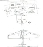
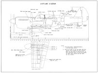
These images are both for the P-40N. I pulled one as a scan from America's Hundred Thousand.
The other is from the P-40N E&M Manual.
The aft end of the Rudder is positively located by the overall length of the aeroplane.
The vertical shift is not so positively located but note that these images do not agree as to the location of the top of the Fin / Rudder from the ground line.
- Ivan.
Attachments
aleatorylamp
Charter Member
Hello Ivan,
It´s frustrating, isn´t it... one of the artist wasn´t too careful, and in this case it´s quite difficult to confirm which one is correct by means of photos. (Going to the museum to measure it would also be impossible... ha ha!).
It happens so often! One of the reasons I´ve delayed re-work on yet another WW1 twin biplane - i.e. the Rumpler G.II/G.III - is that the G.II is said to have had unstaggered wings perpendicular to the fuselage like the G.I, and that only the G.III had refinements like backwards stagger and backwards slanting wings - like an arrow - I don´t remember the term used. It´s not "taper", as the wings have the same width at root and tip.
Anyway, then, in the drawings, I see the G.II´s wings also slanting backwards from the perpendicular line! So... the next step is to try and delucidate this from the few availble photos.
Never a dull moment - and good luck with your deductions!
Cheers,
Aleatorylamp

