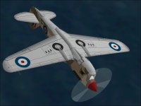
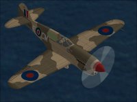
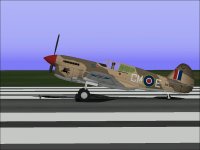
Warhawk

Merlin versus Allison

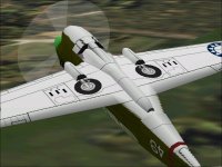
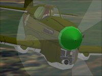
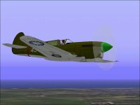
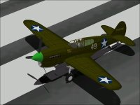
The Merlin Warhawk model is pretty close to completion at this point.
It will represent a P-40F-1. The F-5 was the first Long Tail version.

A couple days ago, I started gathering information for the Flight Model for the F-1.
As one might expect, the majority of the changes are to the Engine Parameters considering that this was basically just an engine swap from the P-40E.

The following are the obvious changes:
The Allison was also designated the V-1710.
The Merlin was designated the V-1640 in US service.

The slight difference in displacement was due to the slightly lesser Bore of the Merlin.
5.4 inch on Merlin versus 5.5 inch on Allison. For the AIR file, each Cylinder would have 137.41326 Cubic Inches displacement.
There was also a difference in Compression.
The Merlin typically used a 6.0:1 Compression while the Allison was typically 6.65:1.
This difference in compression might explain why it was easier to supercharge the Merlin.

Both engines had a maximum of 3000 RPM which makes the next item a bit surprising.
The Propellers appear to be the same across the two models, but....
The Reduction Gearing on the Allison was 0.500 while the Merlin installed in the Warhawk was 0.447
The Pitch Range also differed slightly from 24.5 to 54.5 degrees in the Allison P-40 to 26.5 to 56.5 degrees for the Merlin.

Take-Off Rating
54.3 inches Hg - 1300 HP - 3000 RPM

Military Rating
48.2 inches Hg - 1240 HP - 3000 RPM

WEP Rating
51.0 inches Hg - 1300 HP - 3000 RPM.

There is a lot more data for power settings available. They differed slightly in British as versus American service.

Listed Climb Rates are barely over 2000 ft/min but typically not for full power operation (48 inches Hg - 2850 RPM)
Maximum speeds are 355-365 MPH but again are not at maximum power settings. One test recorded a maximum speed of just over 370 MPH which was probably done at maximum power.

To Be Continued.....
 
Hello Aleatorylamp,

Your description of the assembly sequence for the Nose section is pretty much correct.
The multi colour assembly sequence isn't a new idea.
I have been using it pretty much since I started and Womble55 commented on it a few years back when I was explaining why I was doing it.

Hello No Dice,

Thanks for the compliment. I do think this will look nice eventually. There is still quite a lot to do.
At the moment, I don't know of anyone else who has actually built a Merlin Warhawk or even a proper Long Tail Warhawk for Combat Flight Simulator. Just removing the Carburetor Scoop isn't really enough to do a real conversion in my opinion but that is all that I have seen out there thus far.

The K model released earlier will probably get thrown out eventually because the Tail isn't quite right and it has inherited all the goofy shapes from the Wylam drawings. That it would be thrown out was expected once I started reworking the E model.

When I have a basic K model Long Tail, the next step will probably be the N model with a cut down Cockpit area. You wanted one by the time of your Birthday, so it will only be a couple years late.

Even the E model will get released again once I correct the theoretical Cowl bleed and a couple texture issues.

This whole Warhawk business and how much time I have spent on it is actually quite funny considering how reluctant I was to even begin working on the first Warhawk because I did not think it was a hot enough fighter.

- Ivan.
 
.....

But for the Engine, Coolant Radiator, and Oil Coolers, the P-40E and P-40F are pretty much identical in equipment and disposable loads.

The Zero Fuel Weight of the P-40F Merlin Warhawk may be calculated from the following information:

7089 lbs - Basic Weight. This includes Trapped Fuel, Trapped Oil, Military Equipment, etc.
180 lbs - Pilot. I believe this is a bit light but this is what is in the manual.
98 lbs - Engine Oil. Some of this will be burned in flight so only 75% (73 lbs) is added.
---------
7342 lbs <--- This will be the value for the AIR File.

+ 888 lbs - Full Internal Fuel.
+ 423 lbs - Ammunition.
-----------
8678 lbs - Loaded Weight.

As a comparison, this is the information for the P-40E:
6702 lbs - Basic Weight. (387 lbs LESS for what is basically just an Engine Change.)
97 lbs - Engine Oil. Negligible difference.

- Ivan.
 
Merlin Flight Testing

A couple days ago, I plugged in the known changes to a copy of the P-40E AIR File to begin working on one for the P-40F.
Last night was a fairly long tuning and testing session to try to get some initial performance numbers.

There are actually several problems with performance modelling the Merlin Warhawk:

First of all, the Merlin's performance advantage over the early Allison was due to its Two Speed Supercharger.
CFS does not really handle multi speed superchargers very well. It really models only a Single Speed Supercharger and does not do that very well.
Multiple Speed Superchargers typically have an altitude at which each speed will achieve its greatest output. Between those peak output altitudes, the power drops lower until the next blower shift creates the next peak.
Unfortunately, CFS only models one peak, so the power output will be much higher than it should at altitudes between the peaks.

Another issue is that the listed performance values are not consistent for throttle settings. Some values are listed for Climb Power, some are for Take-Off Power and some are for Military Power.

Yet another issue is that a few of the numbers simply do not make sense.
The P-40F is listed as achieving a maximum speed at Sea Level of barely over 300 MPH.
This is slower than for the Allison P-40s even though there is more engine power even at Military Rating.
At its critical altitude of 20,000 feet, it was quite a bit faster than the early Allison P-40s with a speed between 355 MPH and 375 MPH depending on the source of data.

My version of the P-40F is now getting the following:
319 MPH at 500 feet with 1252 HP. (Take-Off and WEP is 1300 HP, Military is 1240 HP.)
369 MPH at 12,500 feet with 1394 HP. (A bit too high. There should be a Supercharger Gear Shift here.)
369 MPH at 15,000 feet with 1295 HP. (High Speed Supercharger should not be peaking until much higher.)
358 MPH at 20,000 feet with 1052 HP. (Not quite enough HP and slightly low speed here.)

My testing protocol was to record a speed as maximum if it did not increase in 15-20 seconds.
If testing allowed more time for speeds to stabilise, the numbers would be 1-2 MPH higher but then again, I am doing this with an autopilot which is not available on the actual aeroplanes.

This isn't a great match but I believe it fairly reasonable for what can be done in CFS.

Next comes the Climb and Service Ceiling tests.....

- Ivan.
 
Hello Ivan,
I´m not able to contribute much here because the technical info is rather high level, but you seem to have achieved quite a good CFS1 approximation!
Cheers,
Aleatorylamp
 
Hello Aleatorylamp,

Regarding Flight Models, usually I get the match much closer than this.
I am not really expecting responses here or suggestions.
I am just documenting some changes to an aeroplane project.
These Technical Descriptions during a build tend to be mostly monologues which is fine.

This isn't really all that high level. You needed the same information on your builds so you should be pretty familiar with it.

- Ivan.
 
Merlin Performance

My version of the P-40F is now getting the following:
319 MPH at 500 feet with 1252 HP. (Take-Off and WEP is 1300 HP, Military is 1240 HP.)
369 MPH at 12,500 feet with 1394 HP. (A bit too high. There should be a Supercharger Gear Shift here.)
369 MPH at 15,000 feet with 1295 HP. (High Speed Supercharger should not be peaking until much higher.)
358 MPH at 20,000 feet with 1052 HP. (Not quite enough HP and slightly low speed here.)

My testing protocol was to record a speed as maximum if it did not increase in 15-20 seconds.
If testing allowed more time for speeds to stabilise, the numbers would be 1-2 MPH higher but then again, I am doing this with an autopilot which is not available on the actual aeroplanes.

This isn't a great match but I believe it fairly reasonable for what can be done in CFS.

Next comes the Climb and Service Ceiling tests.....

The Merlin Warhawk got some more tuning this morning.
Mostly it was to adjust the Service Ceiling a bit higher than the 32,000 feet I was getting originally.

The new numbers are as follows
318 MPH at 500 feet with 1252 HP.
368 MPH at 12,500 feet with 1388 HP. (Still A Bit Too High.)
373 MPH at 15,000 feet with 1344 HP.
371 MPH at 17,500 feet with 1221 HP.
367 MPH at 20,000 feet with 1102 HP. (This is about where I wanted it to be.)

Maximum Climb is 2790 feet/minute at 7,000 feet.
This is about 300 feet/minute higher than the target but there is a lot more power at medium altitudes than there should be because there is no blower shift point.

Service Ceiling is 34,100 feet which is about where it should be but absolute ceiling is barely over 34,200 feet.
This was done by autopilot and the aeroplane is very unstable above 32,000 feet so the service ceiling when flown without autopilot should be a lot lower.

In my opinion, this is probably very near the target performance. It can certainly be tuned a bit more but the differences would not be very meaningful.

- Ivan.
 
Merlin Radiator

I believe this post was lost with the recent crash:

The Merlin Warhawk's textures were also adjusted a bit especially around the Radiator and Oil Coolers.
At this point, the aeroplane really needs a more appropriate paint scheme. I doubt any Merlin Warhawks ever carried Chinese Nationalist insignia.

- Ivan.
 

Attachments

  • F-UndersideTextures.jpg
    F-UndersideTextures.jpg
    69.1 KB · Views: 0
  • F-NewRadiators.jpg
    F-NewRadiators.jpg
    51.2 KB · Views: 0
  • F-NeedsNewPaint.jpg
    F-NeedsNewPaint.jpg
    41.1 KB · Views: 0
United States Army Air Forces

Recent changes to the Merlin Warhawk have been to begin the SCASM process in order to use BMP textures which accept more tools for editing.

After doing the initial SCASM conversion, I found that the Carb Intake appeared a bit small, so that was also increased in size followed by another SCASM treatment followed by another model edit followed by.... (You get the picture...)

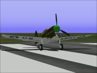
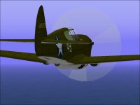
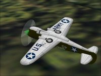
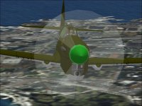
The USAAF paint scheme for the Merlin Warhawk was updated over the last few days which was a lot easier to do using PCX and BMP textures. There is one more paint scheme in the works and that one will be a bit more complicated.

There are quite a few things left to complete:
Completion of the SCASM process
A new Control Panel
Checklist
Performance Testing and Documentation.

- Ivan.
 

Attachments

  • F-USArmy1.jpg
    F-USArmy1.jpg
    49.8 KB · Views: 0
  • F-USArmy2.jpg
    F-USArmy2.jpg
    42.5 KB · Views: 0
  • F-USArmy3.jpg
    F-USArmy3.jpg
    39.4 KB · Views: 0
  • F-USArmy4.jpg
    F-USArmy4.jpg
    60.2 KB · Views: 0
  • F-BiggerCarb.jpg
    F-BiggerCarb.jpg
    77.1 KB · Views: 0
Last night, the Interior Views were corrected.
What remains now for SCASM is just to adjust the animations.
No point in posting screenshots since nothing changed from an exterior view.

The process taken with the Merlin Warhawk seems to be pretty good. It is still based on least commitment but allows a choice of tasks to make progress without forcing a single course of action.

- Ivan.
 
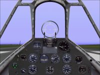
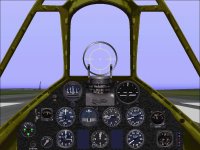
New Instrumentl Panel

The last couple of days has been spent working on a better looking Instrument Panel for the Warhawk.

I had been using a slightly modified stock P-51D Panel up to this point.
Although the panel is functional, the appearance has never been quite right.
I do not believe it is possible to get both functionality and appearance in a good Panel for CFS for some aircraft.
The biggest issue is that the various instruments and controls are distributed in many locations in the cockpit but typical CFS aeroplanes only have a Main Instrument Panel and an Engine Control Panel.
Many instruments also do not have an equivalent in the stock gauges and some do not make sense to include.

This Control Panel is based on the background for the stock Spitfire Mk.IX with instruments selected based on functionality and appearance.

Here are a few characteristics I know are incorrect and likely will remain so:

1. The Fuel Selector does not look like the one here and is not in this location on the real aircraft.
2. There is a Suction / Vacuum Gauge that has not been included.
3. The Magneto and Starter Switch are not on the upper / visible part of the panel on the actual aircraft.
4. There is no Trim Gauge on the control panel.
5. The Clock is located where the Compass would have been and the location of the Clock is taken by the Magneto Switch.
6. There is no Landing Gear Warning Light. I could not find an equivalent in the stock gauges.
7. The Panel Background colouring is not as good a match as I would like. Perhaps this can be fixed....

- Ivan.
 

Attachments

  • F-NewControlPanel.jpg
    F-NewControlPanel.jpg
    82.6 KB · Views: 0
Updated Control Panel

Here is an updated version of the Warhawk Control Panel with Gauge sizes and locations modified slightly and a heavily edited Background. Only stock Gauges are used at this point. The Canopy Frame colour is a best try at this point and perhaps will yet be modified in the future.

I believe that at this point, it is a pretty good combination of functionality and appearance.
Note that for appearance, most of the Gauges came from the P-47D.

Next step is to make some changes to the panel for Test Flying....

- Ivan.
 

Attachments

  • F-ControlPanel.jpg
    F-ControlPanel.jpg
    90.6 KB · Views: 0
Hello Aleatorylamp,

In reality, there probably was no "Curtiss" signature in that location.
We don't really know because where I put it is the sheet metal UNDER the actual Black Control Panel and that area would normally be hidden under the Gun Sight.
The Spitfire Gun Sight is much smaller so there is the space underneath.

I also believe this is pretty good balance between functionality and authentic appearance.
There are actually lots of little missing things such as Coolant Warning Lights, and a bunch of little things added,
The tag "FUEL" should really read "FUEL SIG." for fuel signal but I could not keep the size of lettering if I added a S or G.
The only change I am still contemplating is increasing the size of the Artificial Horizon.

I believe this will be used in future versions of the P-40 and possibly even retrofitted back to the P-40E as an update.

- Ivan.
 
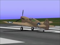
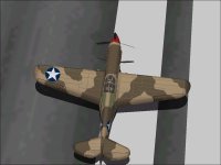
Desert Paint

The Technicians in the Paint Booth have been busy over the last few days.
Last night was a marathon session where the Camouflage was matched up between various pieces of the Aeroplane.

This may not be the best way to do it, but essentially the painters have to paint each piece before it is fitted to the Aeroplane and when there is a mismatch as there usually is, the piece is removed to be repainted and reassembled.

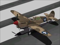
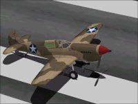
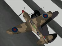
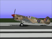
This result is actually pretty close to the typical Desert scheme used by the RAF and USAAF though I have taken a few liberties which I believe improve the appearance.
Other personal and unit insignia still need to be applied.

- Ivan.
 

Attachments

  • F-DesertBasePaint2.jpg
    F-DesertBasePaint2.jpg
    47.3 KB · Views: 0
  • F-Desert1.jpg
    F-Desert1.jpg
    38.2 KB · Views: 0
  • F-Desert2.jpg
    F-Desert2.jpg
    52.6 KB · Views: 0
  • F-Desert3.jpg
    F-Desert3.jpg
    47.2 KB · Views: 0
Hello Ivan,
Nicely fitting camo patterns! I feel they always give a very professional look.
As regards names on the instrument panel, I also like putting them in, just to add a bit of ambience, even if on the real aircraft they weren´t there or as visible.
Cheers,
Aleatorylamp
 
The first paint scheme was a Generic US Army Olive over Neutral Gray.
The second scheme was US Army Desert Sand and Dark Earth over Sky (Gray)
The third and final scheme which I just finished is RAF Desert Sand and Dark Earth over Sky (Gray).

The RAF Desert scheme is actually the hardest because there were so many little changes over time and it is quite possible to get a combination that could never have happened.

There were a few others, but I think this combination should be good enough for release.
Should I release just one version with all three schemes or two versions with contrasting schemes as I did with the P-40C?
I am tending towards two.....

- Ivan.
 

Attachments

  • F-RAFDesert1.jpg
    F-RAFDesert1.jpg
    50.2 KB · Views: 0
  • F-RAFDesert2.jpg
    F-RAFDesert2.jpg
    44.6 KB · Views: 0
  • F-RAFDesert3.jpg
    F-RAFDesert3.jpg
    46.6 KB · Views: 0
  • F-RAFDesert4.jpg
    F-RAFDesert4.jpg
    43.8 KB · Views: 0
There are a couple parts of the camouflage pattern that are questionable.
Some are intentional and done under artistic license.

ONE section is pretty close to the painting guide for P-40 models:
The port side of the Tail under the Horizontal Stab clearly shows as Dark Earth, but....
in photographs, This shape appears to resemble a dark shadow rather than dark paint.

The Wing Root and Fillet on the starboard side should also have the dark pattern moved forward a bit.

- Ivan.
attachment.php
 

Attachments

  • F-RAFDesert2.jpg
    F-RAFDesert2.jpg
    44.6 KB · Views: 0
Back
Top