Warhawk

Hello Ivan,
From your comparison of the performance of the different aircraft, it is interesting to see how different top-notch manufacturers who were operating at cutting-edge technology, were successful in different areas, each being able to come out with peak performance in specific areas, and how it was extremely difficult or almost impossible to come out with a general all-round winner that beat all otheres in all aspects.
Cheers,
Aleatorylamp
 
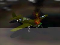
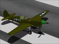
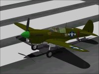
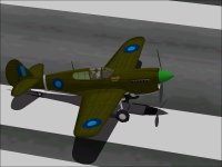
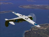
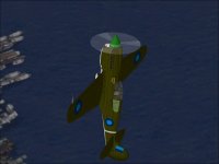
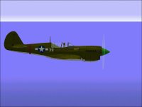
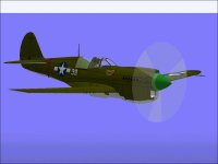
The P-40N model was pretty much completely last night and this evening most of the textures were adjusted.
My computer is still acting up rather badly which even made screenshots difficult.

What still remains is the SCASM processing, Flight Model, Damage Profile, and even a New Control Panel.
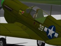
The N model used at least two Control Panels that were significantly different from earlier models.
The internal Canopy Frame also needs to be built and I will probably be adding another paint scheme before I am done.

-Ivan.
 

Attachments

  • P-40N-EngineFire.jpg
    P-40N-EngineFire.jpg
    34.6 KB · Views: 0
  • P-40N-Paint1.jpg
    P-40N-Paint1.jpg
    47.8 KB · Views: 0
  • P-40N-Paint2.jpg
    P-40N-Paint2.jpg
    53.2 KB · Views: 0
  • P-40N-CockpitArmour.jpg
    P-40N-CockpitArmour.jpg
    53.1 KB · Views: 0
The Vent Window

The late model P-40s had a small vent window on the forward left side that could be opened in flight.
I have always thought this was a peculiar design and rather ugly but it was an obvious recognition feature.
This was an asymmetric design and only on the left which causes some issues when thinking of an aeroplane as a nice symmetrical object.

My development computer is misbehaving so it took a few tries to make things work.

Note that at this point, the Internal Canopy Frame Component is not reversed. It makes sense to stay in AF99 when just building the pieces.

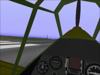
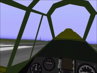
Here is a comparison between the views with and without the Vent Window.
If this is any indication, then the additional framing did not greatly impact the view from the Cockpit.

Next come changes to the Instrument Panel background to add the new Frame and a bit of a redesign of the entire panel to more closely resemble the N version.

- Ivan.
 

Attachments

  • NoVentWindowInterior.jpg
    NoVentWindowInterior.jpg
    43.3 KB · Views: 0
  • VentWindowInterior.jpg
    VentWindowInterior.jpg
    45.5 KB · Views: 1
P-40N - Flight Modelling Data

This Project being built for Combat Flight Simulator is intended to represent a "Generic" P-40N.
Besides the P-40N-1 and P-40N-40, the other models were quite similar and differing only slightly (from the CFS Viewpoint) in equipment.

The P-40N-1 was a lightweight version which didn't have a cut down rear fuselage and looked more like a P-40M.
Differences were in internal equipment and reduced armament.

The P-40N-40 did not look any different from the earlier versions but combined the engine controls into a single simplified control.
There were fewer options for the pilot. The problem with representing this design is the lack of panel instruments that can perform the proper functions of combining propeller pitch and throttle.

Depending on the source and variant, engine power differed a bit in the P-40N.
The Take-Off Power was 1200 HP at 3000 RPM and achieved with 52" Hg Manifold Pressure.
WEP from one source was 1360 HP at 3000 RPM.
The Pilot's Manual shows WEP as 1480 HP at 3000 RPM with 57" Hg Manifold Pressure at 10,000 feet. This is the number I will be aiming for.
Military Power was 1125 HP at 3000 RPM with 44.2" Hg achieved at 17,000 feet.

Cruise Power is specified at Auto Rich and Auto Lean settings which I don't know how to represent in CFS so although a number will be added to the Check List, it may have a bit less meaning than it would imply.

Armament will be a full 6 x .50 Cal MGs with the maximum ammunition loadout
Bomb Load will be 3 x 500 Pound as was typical for a late model P-40.
The model will have all three internal fuel tanks unlike some of the early Ns that had he forward tank removed.
Capacity may have varied slightly with fuel tank construction but that will not be taken into account.

Weights will be for the P-40N-25 which are pretty typical:
6717 Pounds Basic Weight
200 Pounds Pilot
60 Pounds Oil -- Note that this is less than for earlier variants.
423 Pounds Ammunition
954 Pounds Internal Fuel
------------------------------
8354 Pounds Gross Weight

The weight used for the AIR file will be
6717 Pounds Basic
200 Pounds Pilot
45 Pounds (75%) Oil
------------------------------
6962 Pounds.

- Ivan.
 
download champ

Hi Ivan,
Have you noticed the downloads on the 2 models?
Indeed remarkable for CFS1 in this day and age.
Cheers,
Aleatorylamp
 
I also am surprised at the number of downloads.
I wonder what it is about this particular model that is so much more attractive than other earlier P-40s I have released because to me, the quality (or lack) is all pretty much equivalent.
After the P-40N model is finished (and before its release), I need to do some testing for the flight model because I see a few faults.
The P-40K with a fin fillet will likely wait until other more interesting projects are done.

- Ivan.
 
Hello Ivan,
Perhaps the high download numbers reflect the interest and expectation generated by the discussions in the thread on how you were improving the P-40, with special emphasis on design accuracy, realistic detail and the flight model, to get it as close as possible to the real plane.
With the amount of information on the aircraft that is mentioned in the posts, it makes downloading a model more enticing, I´d say.
Cheers,
Aleatorylamp
 
I just take the higher download count as an oddity.
It doesn't remotely come close to the 10,000 downloads I had seen on other less detailed models years ago.

There is nearly the same discussion and information on just about every project I work on, so that probably isn't the reason.
As always, I build these models because I like doing it, and the download count really isn't that important (which is why I have never uploaded anything to Simviation or Flightsim.com.)

Not important but still nice to see because it is a form of compliment.....

:untroubled:
- Ivan.
 
SCASM cockpit, texture and animation tweaks were completed last night.
Next comes some more texture modifications and then then comes a major revisit to the flight model.
I am also debating on a Russian and a RAF Desert texture for this export only version.

- Ivan.
 

Attachments

  • M-1.jpg
    M-1.jpg
    43.9 KB · Views: 0
  • M-2.jpg
    M-2.jpg
    73.4 KB · Views: 0
  • M-3.jpg
    M-3.jpg
    40.5 KB · Views: 0
P-40N Flight Testing

The prior post was about the P-40M export-only version.
Now we will continue with the P-40N which still needs SCASM Processing even after all this time.

One might wonder why I am jumping back and forth between the M and N versions.
It is because from a visual model standpoint, the M is only a very minor change from the prior K version.
To get the N, it is easier to modify the M model than the K model.
The problem with finishing the M is that there is much less performance and other data available as compared to the N.
Since both aeroplanes use the same V-1710-81 engine, it makes more sense to tune the engine and performance for the N and export the engine back to the M version.

The version that will be built is the P-40N-15-CU because it has the proper combination of features I intend for this project.
The P-40N-20 was equipped with the Allison V-1710-99 which had simplified engine controls and a simplified Instrument Panel.
At this time, the P-40s were still leaving the factory with camouflage paint; It was not until the production of the last P-40N-40s that no paint was applied at the factory.

As usual, there is a bit of conflicting information on the P-40N.
How fast was it really?
The P-40N-1 was able to reach 378 MPH at 10,500 feet but was also the lightest version with about 450 pounds less loaded weight than later versions.
This did not make it the most effective version because the weight was mostly fuel, ammunition and guns as was the case for the P-40L.
Later versions were supposedly quite a bit slower with one version reaching only 350 MPH at 17,000 feet.

Next step was to do some Engine Tuning starting with the V-1710 from the earlier P-40K Hawk 87B Project.

.......
 
Superchargers and War Emergency Power

The earlier Allison V-1710-39 and -73 (F3R and F4R) engines were fairly tolerant of over boosting.
The Allison Engine company agreed to permit settings as high as 60 inches Hg at which point these early engines were putting out around 1570 HP.
Some operators claimed to be running near 70 inches Hg for around 1700 HP....
This was from an engine that was only rate at 1150 HP.


The V-1710-81 installed in the P-40M and P-40N had higher supercharger gear ratios and was not nearly as tolerant of over boosting.
Its maximum output was 1480 HP at 57 inches Hg from an engine rated at 1200 HP.

From the standpoint of balance, these over boosted settings should be limited in some way and should be considered "War Emergency" settings.

With War Emergency Power in Combat Flight Simulator, we have yet another problem: It is not implemented correctly.

A Supercharger is used to pump additional air into the intake of an Engine.
Engines because of structural strength limitations have maximum manifold pressure limitations.
At Sea Level, the supercharger is generally capable of pumping much more air than the engine can take.
As the aircraft gains altitude, the outside air pressure drops and the supercharger's excess capacity is reduced.
At some point, the outside air pressure is low enough that the supercharger operating at full capacity is only able to pump enough air for the engine to reach its maximum Manifold Pressure.
This is the Critical Altitude.

War Emergency Power is higher throttle setting than normally allowed.
This higher setting may be due to the use of an anti-detonant / charge cooler such as Water, Methanol-Water, or additional Fuel injected into the engine or
it may require no anti-detonant and just rely on the heat-soaking ability of the engine and its cooling system.

The crucial point is that with the exception of additional oxidizers such as Nitrous Oxide (GM1 or NoS), there is no additional supercharger capacity.
Above the Engine's Critical Altitude, there IS NO ADDITIONAL CAPACITY from the supercharger than can be made available with War Emergency Power.
Unfortunately Combat Flight Simulator's WEP does not work that way.
It adds additional manifold pressure regardless of altitude.

We shall see very shortly how this affects this flight model.

.......
 
Allison V-1710-81

The Allison V-1710-81 had higher supercharger gearing than earlier engines.
As such one would have expected more power to be absorbed by the supercharger.
In this case, because I expected the power drop-off to be slower than for the earlier Allisons,
the Torque was reduced instead of increasing the Friction.

Here are the results:
Target: 1200 HP at 3000 RPM (52.0 inches Hg) at Sea Level (Take-Off Rating)
Actual: 1210 HP at 3000 RPM (52.0 inches Hg) at Sea Level (500 Feet)

Target: 1480 HP at 3000 RPM (57.0 inches Hg) at 10,000 feet (WEP)
Actual: 1479 HP at 3000 RPM (57.0 inches Hg) at 10,000 feet (WEP)

Target: 1125 HP at 3000 RPM (44.2 inches Hg) at 17,000 feet (Military Rating)
Actual: 1120 HP at 3000 RPM (43.2 inches Hg) at 17,500 feet (Normal Maximum)

Unfortunately because of CFS handling of WEP, we have this:
Actual: 1384 HP at 3000 RPM (51.0 inches Hg) at 17500 feet (WEP)

Speeds:
Max: 312 MPH @ Sea Level
WEP: 322 MPH @ Sea Level
These numbers are fairly reasonable but are a bit slower than the earlier Warhawks
Without WEP, this is slightly slower than the Merlin Warhawk but with WEP it is slightly faster.

WEP: 371 MPH @ 10,000 feet
This is about where I would have wanted it.

Unfortunately there is also the following:
WEP: 389 MPH @ 15,000 feet with 1528 HP....

Service Ceiling is around 32,700 feet with Absolute Ceiling near 33,500 feet with 50% Fuel.

Other than the high altitude WEP effects, this seems pretty close.
Since WEP is only available for 10 minutes, it is good for about 3 speed runs starting at maximum non-WEP speed.
With the extra power, this aeroplane would have much more agility than it should between 10,000 and 20,000 feet.

- Ivan.
 

Attachments

  • WarhawkN-SpeedRun1.jpg
    WarhawkN-SpeedRun1.jpg
    27.3 KB · Views: 0
  • WarhawkN-SpeedRun2.jpg
    WarhawkN-SpeedRun2.jpg
    31.3 KB · Views: 0
".....A Supercharger is used to pump additional air into the intake of an Engine.
Engines because of structural strength limitations have maximum manifold pressure limitations.
At Sea Level, the supercharger is generally capable of pumping much more air than the engine can take.
As the aircraft gains altitude, the outside air pressure drops and the supercharger's excess capacity is reduced.
At some point, the outside air pressure is low enough that the supercharger operating at full capacity is only able to pump enough air for the engine to reach its maximum Manifold Pressure.
This is the Critical Altitude. ....."

"At Sea Level, the supercharger is generally capable of pumping much more air than the engine can take."
True, but I don't believe you can model the wastegate in the FS model. This is a proportional air valve that is left open at low altitudes to just dump most (if not all) of the (turbo)supercharger output as it is basically not needed at this point. Thus, the engine basically runs only in normally aspirated state at atmospheric pressure at sea level to a couple thousand feet altitude.

"As the aircraft gains altitude, the outside air pressure drops and the supercharger's excess capacity is reduced." My understanding of the process is that the (turbo)supercharger output remains constant at rated output by design through the altitude range. However, the wastegate now starts to close as the aircraft ascends in order to maintain the manifold pressure to contribute to engine power. Thus, the dumping is gradually closed off and the (turbo)supercharger output is now gradually applied to the engine.

"At some point, the outside air pressure is low enough that the supercharger operating at full capacity is only able to pump enough air for the engine to reach its maximum Manifold Pressure.
This is the Critical Altitude. ....."

When the wastegate is fully closed, the (turbo)supercharger is now applying rated output fully to the engine. Measured by the MP rating (and maintaining it) at some power setting (military power ?), the "Critical Altitude" has been reached. Any further increase in altitude will result in decreased MP/engine power as the (turbo)supercharger has now reached its limitation due to:
a.) the outside air pressure.
b.) the design parameters of the (turbo)supercharger.
 
Supercharger Implementations

Hello GLH,

Welcome to Combat Flight Simulator.

Thanks for some additional explanations.

I was being deliberately vague with the mechanics of specific implementations because the actual implementations vary in lots of ways.
Your mention of a Waste Gate tells me that you are probably discussing Turbo Superchargers which are compressing only Charge Air.
Some of the Superchargers being discussed here are compressing Air and FUEL and would not be dumping the excess out the side.
Some others such as those on the Daimler Benz DB 600 series engines used a fluid clutch with slippage that varied with altitude.
Others are just throttle limited.

The major point in this whole supercharger discussion is that past the critical altitude, WEP cannot provide any more boost whether it is on or not.

- Ivan.
 
Incorporating WEP in the Throttle Gauge bitmap

Hello Ivan,

For my current Baltimore Project, CFS1 WEP impementation and aircraft ceiling is also a problem.

After reading this latest interesting exchange on turbo-superchargers here on this thread, and also having noted the way that your MitchellC .air file includes WEP within the normal procedural maximum power, it occurred to me that this could be the most feasible solution. Without using the CFS1 WEP option, ceiling performance would remain unaffected.

Of course, it is not a new idea to include the full Manifold Pressure in the Engine Parameter Section, so as to get full HP at normal full throttle, leaving WEP without activation, but one could then edit the throttle gauge bitmap with a red area at the end of the Throttle Lever Travel: This would define the WEP area, not to be invaded in normal circumstances! Of course it would have to be carefully dimensioned using the Beckwith gauge to get the position right.

Also, simmers would obviously have to be careful using the throttle lever in order to maintain realism, because in this case, the engine would not break down after time runs out if the throttle lever stays in the WEP area. Basically, this would be the only drawback for this possible solution.

If this idea is useless, please ignore this post!

Cheers,
Aleatorylamp
 
Hello All,

I had meant to acknowledge it, but forgot: GLH actually gave a pretty good explanation of the way Turbo Superchargers work.
The only disagreement I had with his comments were about Turbocharged aeroplanes just trying to maintain naturally aspirated power levels.
I believe that all the Turbocharged aeroplanes of the time were equipped with an additional mechanical supercharger and were running manifold pressures well above 30 inches Hg which means they were running higher than naturally aspirated settings.

Hello Aleatorylamp,

The problem with the bitmap "Gating" that you are describing is that the non-WEP throttle position limit would change with altitude.
Perhaps we can build a Throttle Gauge that would enforce this kind of setup?
That would also presume that the Engine Control Panel was the only control available.

- Ivan.
 
Hello Ivan,

The idea would only be valid if this were to be a better solution than to have a more-or-less inaccurately adjusted ceiling with WEP.

The only suggestion for a red WEP zone on the Throttle gauge bitmap, would be to have an additioinal initial orange zone which would mark the transition zone, depending on altitude, between maximum normal throttle and WEP positions. Here there could be three black lines indicating low, medium and high altitude for the beginning of the WEP position.

I suppose Take-off power, which is also a 5-minute affair, would be in the WEP area rather than within the normal maximum power range.

An ideal situation for this idea to work would be if normal maximum power were to coincide with an 80% or 90% throttle positions, because of the keyboard keys that can be used, so for example take-off would be with 90%, normal maximum with 80%, and WEP with 100%. That would be very convenient...

The first thing to do would be to see where the maximum normal power lies with the Beckwith gauge giving a normal Hp reading at low, medium and high altitudes. It will be curious to see what percentage Hp it would be.
Of course the equivalent of 100% normal power percentage changes because 100% would in this case include WEP.

Perhaps, as a starting point, I´ll experiment a bit changing the stock P47 air file and see how it affects power and how the throttle gauge position reacts, if WEP is included in the normal procedural performance range.

Cheers,
Aleatorylamp
 
P47D WEP study, initial findings.

Hello Ivan,

I installed a duplicate of the stock P47D for comparison, with a modified .air file which included WEP within the normal throttle lever travel. I raised the MP parameter from 52 to 56, and set WEP at 0.

I conducted trials every 5000 ft, and noticed that normal maximum power with the modified .air file was at 92% of maximum throttle position, with 52.1 Mpsi.

This appeared to be consistent upto 25000 ft. The stock .air file maintained its 52-56 Mpsi values, and the modified one kept 52 Mpsi for 92% power, so a red zone on the throttle gauge bitmap may be of some use for this kind of WEP incorporation into the normal travel of the throttle gauge.

As of 30000 ft, however, the modified .air file could only provide the non-WEP power of the stock .air file, but needed 100% power to do so.
Update: As critical altitude for the P47D is 27000 ft, it´s logical.

This would mean that a red zone on the throttle gauge only indicates an effective and careful use of WEP upto this altitude, after which full power can be maintained with full forward throttle as WEP is no longer operative.

30000 ft: Stock .air file Mpsi fell to 45.1 and 49.6 (WEP).
Modified .air file, 92% throttle fell to 42.3 Mpsi, and 100% throttle was only with 44.7 Mpsi, and gave the non-WEP power of the stock .air file.

At 35000 ft: Stock .air file Mpsi fell to 35.5 and 39.1 (WEP).
Modified .air file, 92% throttle fell to 33.5 Mpsi, and 100% throttle was only with 35.5 Mpsi, and gave the non-WEP power of the stock .air file.

40000 ft: Stock .air file Mpsi fell to 27.9 and 30.7 (WEP).
Modified .air file, 92% throttle fell to 26.2 Mpsi, and 100% throttle was only with 27.9 Mpsi, and gave the non-WEP power of the stock .air file.

Although the ceiling is quoted as 42000 ft for the P47D, neither .air file was able to maintain this altitude.

At altitude, however, as one would have expected, the modified .air file seems to deal more realistically with the WEP power.

I thought this information is quite interesting, and may be of some use.

Update:
P.S. I did the same comparison with the P51D and here the normal max. was at 90% throttle if WEP was included in the throttle lever travel, and the altitude at which WEP started to dwindle was 25000 ft, as P51D critical altitude is 24000 ft. Actually the 90% position is quite convenient because of key "9" for normal maximum throttle.
In conclusion, this could perhaps mean that in CFS1, changes in altitude below critical altitude would not affect the throttle position at which WEP would start if WEP were implemented within the normal throttle lever travel, and hence would not require making a special throttle gauge which takes altitude into account for the threshhold between WEP and non-WEP.

Cheers,

Aleatorylamp
 
Last edited:
SCASM edits are now finished for the P-40N.
Most of the Hawk 87 series has been nearly the same as far as location of pieces in the SCASM SCX source code.
Sometimes one or two pieces may need to be located because their address (and thus the Label) has changed from the prior project.
This project has had the most changes of any in the Hawk 87 series.

The Camouflage / Markings need a few edits and possibly an alternative paint scheme added.
The DP file is not significantly changed from any of the prior versions.

The most significant task remaining is to tune the low speed handling characteristics to remove some odd behaviour.

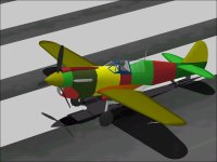
The screenshot shows what happens when the MDL is edited to use new textures and the new textures have not yet been created.....

- Ivan.
 

Attachments

  • P-40N-SCASM_ReTexture.jpg
    P-40N-SCASM_ReTexture.jpg
    48 KB · Views: 0
A duplicate Allison V-1710-81 engine was built up for the P-40M as well.
There was a slight bit of difficulty when power readings were close but not exact.
It turns out the technician doing the final assembly had included some mismatched accessories which was soon corrected.

The aeronautical engineers are doing some testing on the P-40N for directional stability.

- Ivan.
 
Back
Top