Warhawk

Very Ambitious

I have also been considering doing ALL of the P-40 versions from the P-40B/C all the way out to the P-40N. The Q also is a consideration, but it would require a substantial rebuild (which is what the real one was) and I am lazy.

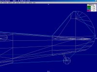
In order to do this, the textures need to be able to support long and short Fuselage variants, AND the monstrously ugly Fin Fillet on the mid series K. I also want the texture layouts to be as close to the same as possible between variants. I had originally arranged the textures VERY tight for the P-40E with almost no wasted space.
When the increased length Tail Cone needed to be fitted in, the Fin could no longer fit onto the same texture file as the Tail Cone. This wasn't a big deal because I had no room to put the texture for the interior of the Canopy Frame for the Virtual Cockpit. Thus one more texture file was added. A couple things like landing gear pieces also needed moved around to fit.
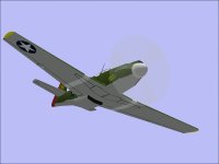
What I had not considered was that the extra length Fin Fillet on the earlier K series would need more room than I had originally planned. A bit more reworking and now I believe I can handle from the D model out through the N model using the same basic layout with some small component variations.

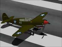
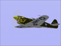
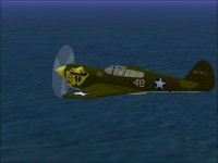
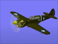
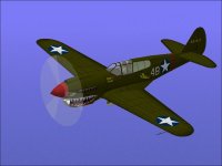
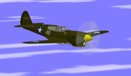
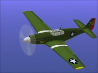
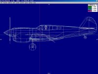
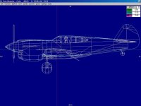
The P-40K also had a minor trip through the Paint Shop and hopefully looks better. I could not find a definitive source for paint standards, so I used a bit of artistic license.

- Ivan.
P.S. My son calls this aeroplane "Rudolf" for fairly obvious reasons.
 

Attachments

  • P-40K_RFHigh.jpg
    P-40K_RFHigh.jpg
    48.4 KB · Views: 2
....and I am lazy.

sorry, i don't buy it.
you are far from lazy.
maybe, a little over extended, but, not lazy.

I have also been considering doing ALL of the P-40 versions from the P-40B/C all the way out to the P-40N. The Q also is a consideration, but it would require a substantial rebuild (which is what the real one was)

this would be a major undertaking,
but, when completed, an interesting package.
i, for one, would like to see it happen.
 
Alaskan Visitor

We had a visitor from Alaska visit our shop today. She claimed to be an artist and wanted to look over the P-40K. She spent a lot of time looking at the P-40 from different angles and drawing and making notes in her sketch pad.

When we stepped out of the shop to analyse results of recent engine tests, she sneaked into our paint booth and tried her hand with our spray guns. By the time we came back into the shop, she was so far along that we decided to let her finish.

We decided it wasn't worth repainting back to the original colours just for flight testing today, so here is the result. The paint wasn't even on long enough to dry when these shots were taken.

We are still trying to decide whether to throw her in jail or hire her for future work.
;-)
- Ivan.
 

Attachments

  • Aleutian_LFLow.jpg
    Aleutian_LFLow.jpg
    32.1 KB · Views: 0
  • Aleutian_LA.jpg
    Aleutian_LA.jpg
    44 KB · Views: 0
Over the last few days, the AIR file of the P-40K gradually took shape. There are a few things about it that surprise me, but I believe that a lot of it is due to the conflicting information about the aircraft.

Maximum Speed at 5000 feet
Actual 320 mph
Model 341 mph

Maximum Speed at 15,000 feet
Actual 362 mph
Model 357 mph (Maximum Speed 363 mph @ 10,000 feet)

Service Ceiling
Actual 28,800 feet (Unknown climb rate. Was it 500 feet/min or 100 feet/min?)
Model 29,900 feet (100 feet/min with 50% fuel and 100% ammunition)

Initial Climb
Actual 2600-2800 feet/min depending on source
Model 2990 feet/min

The general handling seems to be quite good. In watching Air Show performances on video, it appears to me that P-40 pilots actually are willing to do more with their aircraft than just low level passes and a few slow rolls. They move much more enthusiastically than your typical WW2 fighter.

Smilo,
A complete set of P-40 models is actually not that far away:
The early P-40 through P-40C have been done.
The P-40D,E, and early K without the fillet are done.
Adding a Fin Fillet gets the mid production short tail K.
The P-40K,M are my current project.
The P-40N isn't that much of a departure from the K.
The P-40F,L with Merlin engines are basically either E or K models with a revised cowl and intake.

Problem is that I can see all the P-40s I have could use some improvements.

- Ivan.
 
P-40K Long Tail

The paint schemes took a bit longer than I thought they would.
The Disney Flying Tiger image didn't quite turn out as well as I had hoped, but the fuselage seemed a bit bare without it.
I am not sure which set of textures I like better.

I had always thought of these mid production P-40s as rather drab, Sad Sack kind of aeroplanes. In doing a little basic research to work on this project, I found that these P-40Ks were probably the hottest version of the aircraft at low altitudes. The Allison engine tolerated boost pressure well above what the manual specified. It became bad enough in practice that the limits in the manuals were adjusted higher (after GM / Allison Division's agreement) though not as high as some pilots were already using.
The Merlin installations had much better altitude performance but were not even close in power at low altitudes. Later Allison engines also reduced maximum manifold pressures because their higher geared superchargers would not stand up to as much boost down low.

I still believe this project could use some improvement but is pretty much releasable as it stands.

- Ivan.
 

Attachments

  • Hawk87BA_LFHigh.jpg
    Hawk87BA_LFHigh.jpg
    38.5 KB · Views: 0
  • Hawk87BT_LFHigh.jpg
    Hawk87BT_LFHigh.jpg
    41.6 KB · Views: 0
.....
The Disney Flying Tiger image didn't quite turn out as well as I had hoped, but the fuselage seemed a bit bare without it.
I am not sure which set of textures I like better.

.....................

I still believe this project could use some improvement but is pretty much releasable as it stands.

- Ivan.

if i might offer an opinion, or two;

ship it, she's a beauty!

as for the textures, i have to disagree.
but first, i need to qualify....
i have always been partial to the Plane Jane,
everyday workman style paint schemes.
i don't think the fuselage seemed a bit bare without it.
i like it. she looks great!

as for the Disney Tiger and the Aleutian Tiger motifs,
i prefer the Disney Tiger.

i've never really appreciated the Aleutian Tiger.
to me, it just looks like a muddled glob of yellow.
a bit harsh, yes. please don't take offense.
i can see that you've spent a lot of time on it.
this does not apply to just your paint.
i have thought that since the first time
i saw the scheme many years ago.
maybe, if i was stationed in the Aleutians,
i would feel differently about it.

as i said above,
SHIP IT!!
 

Attachments

  • PlaneJane.jpg
    PlaneJane.jpg
    27.1 KB · Views: 0
Hi Smilo,

I actually uploaded it last night....
;-)

The Disney Flying Tiger was a poster sized print that was sent to the AVG in China. They pasted them onto the sides of their aircraft. The problem is that in CFS, the pixels are kinda large so if the image is about the right size on the aeroplane, it looks a bit pixelated up close.... I may work on it again, but not for a while.

- Ivan.
 
Smilo,

You're right. I should have sent a copy to No Dice. Last night, I was just a bit too tired after trying to write something descriptive for the P-40K.
My son had my computer most of the day for online games and right now, the ZIP file is on a flash drive that I can't get to without waking up Anna Honey. Doing THAT would not be wise....

FWIW, Tonight, I thought I would demonstrate proper flying technique for a simple take-off, once around the island and landing to my son after his online games. He was sitting still and watching so intently (which is unusual). I executed a proper take-off while staying near the center of the runway.
On the approach to land, I was dragging it in pretty slow for a nice three-pointer, found I was a touch low and managed to stall and crash in a nice looking fireball just short of the runway....

I had forgotten that at low speed, the P-40 has all kinds of trim changes.

- Ivan.
 
Now that the Workshop's Assembly Line is cleared of the P-40K (at least for a little while), What should take its place in the P-40 series?
For a Long Tail, we can go next to a P-40N. For the Short Tail, we can go next to either a revised P-40E with WEP and some graphical fixes or a P-40F with a Merlin, or even a Short Tail P-40K with a Fin Fillet. Or perhaps the Hawk 81s also need a canopy frame?

- Ivan.

Any P-40/Merlin version would be great. It would also give you an opportunity to explain to us why it was not as successful a pairing than it was for the P-51. Was the P-51 lines so superior to the Curtiss? After all, North American bought the plans of the P-40 before building their pony. Some even accused them of copying, which is absurd in face of the greatly enhanced performances of the Mustang, Allison or RR versions.
 
Off the top of my head, I think it was down to the aerodynamics. The P51 had much better streamlining and that all important laminar flow wing whereas the P40 was fairly modern but still old technology. The P40Q tried to address these problems which to some extent they did but there was no point changing production over to something that was just as good as what they already had...the P51. As quoted in several books, the P40 was a damn good second choice.
 
Aerodynamic Differences

Any P-40/Merlin version would be great. It would also give you an opportunity to explain to us why it was not as successful a pairing than it was for the P-51. Was the P-51 lines so superior to the Curtiss? After all, North American bought the plans of the P-40 before building their pony. Some even accused them of copying, which is absurd in face of the greatly enhanced performances of the Mustang, Allison or RR versions.

Off the top of my head, I think it was down to the aerodynamics. The P51 had much better streamlining and that all important laminar flow wing whereas the P40 was fairly modern but still old technology. The P40Q tried to address these problems which to some extent they did but there was no point changing production over to something that was just as good as what they already had...the P51. As quoted in several books, the P40 was a damn good second choice.

I was debating on which message to reply to. Hopefully this looks OK.

Hubbabubba,

The actual plans that North American were REQUIRED to buy were not those of the P-40, but rather of the P-46 which was a more recent development that showed promise. The big problems with the P-46 were that the airframe was a bit on the heavy side and that the Allison engine didn't have enough power to haul that mass around but it was still a faster aeroplane on the same engine power as the P-40. Although North American bought the plans, there is no evidence that they influenced the Mustang / Apache design at all.

Womble55,

Aerodynamics was certainly ONE factor but in my opinon was not the DOMINANT factor. Aerodynamic / streamlining generally affects maximum speed but perhaps not much more. With the same engine, the Mustang was superior in speed to the P-40 but it was just as superior to the Spitfire when equipped with the same engine:

The Mustang Mk.I and P-40E were both equipped with the Allison V-1710-39 (F3R) with the same horsepower ratings. The maximum speed of the P-40E was around 345 mph while the Mustang I could hit about 380 mph on the same power. The climb rates of the two aircraft were quite similar as were their weights.

The Mustang Mk.III (P-51B/C) and Spitfire Mk.IX were both equipped with Merlin 60 series engines of nearly the same power. The maximum speed of the Mustang III was about 440 mph while the Spitfire IX could only achieve about 410 mph. The Spitfire could climb over 600 feet per minute faster mostly because it was significantly lighter.

An even more interesting comparison is the Lavochkin La-5FN and La-7. Both aircraft had the same engine. Their planforms and size are nearly identical. The La-5FN could hit about 405 mph. The La-7 with a laminar flow wing and repositioned oil cooler (!) could hit about 425 mph.

A bit off topic, but WHY was the Mustang so much faster on the same engine power?
First, it did have a laminar flow wing section and that probably helped a lot but also cost something as well. The Mustang was less agile than the P-40 or the Spitfire probably because the Laminar Flow Wing had a significantly lower maximum Lift Coefficient when compared to the older designs.
A second aerodynamic factor was the Coolant Radiator which used something called the "Meredith Effect" to add thrust on the exhaust side to offset most of the cooling drag. I believe this was the more significant factor.

The prototype P-40 ALSO had a rear mounted Coolant Radiator which was moved forward because of fears that it would be vulnerable to debris from the the propeller wash. The Lavochkin La-7 moved its Oil Radiator back from under the cowling to under the rear fuselage even though it would make it more vulnerable with longer oil lines to weapons fire.

....
 
Engine Power

The most significant reason the P-40 didn't get as much of a gain as the Mustang did with the installation of the Merlin engine was simply that the two aircraft did not get the same version of the Merlin:

The P-40E had an Allison V-1710-39 (F3R) engine with a Single Stage - Single Speed Supercharger.
Its critical altitude was 12,000 feet at which it could produce 1150 HP at Military rating.

The P-40F received the Packard Merlin V-1650-1. This had a SINGLE Stage - Two Speed supercharger.
Its critical altitude at low speed was 10,800 feet at which it could produce 1240 HP at Military rating.
Its critical altitude at high speed was 18,000 feet at which it could produce 1050 HP at Military rating.
At 18,000 feet, it was making about 200 HP more than the Allison F3R did at the same altitude.

The P-51B received the Packard Merlin V-1650-3. This had a TWO Stage - Two Speed supercharger.
Its critical altitude at high speed was 26,000 feet at which it could produce 1210 HP at Military rating.
Its significantly higher critical altitude was the main reason it gained so much performance.

The Merlin installed in the P-40 was pretty similar to the one installed in the late Hurricanes while the Merlin in the Mustang was most similar to that of the 60 series Merlin Spitfire. The Hurricane was never noted for great altitude performance either.

As a side note, The P-51A which was easily the best performing Allison Mustang had the Allison V-1710-81 (F20R).
It also had a Single Stage Single speed supercharger but with the critical altitude increase to 14,600 feet (1125 HP Military rating).
It was considerably less capable at lower altitudes than the earlier Allison F3R and F4R engines and had a WEP MP limit of 57" Hg instead of the earlier engines' 60" Hg.

The Merlin Mustang was apparently a bit less aerodynamic than the Allison Mustang as well. The Merlin 60s produced a bit more power at low altitudes than the Allison F20R, but the Allison Mustang was a bit faster up to 10,000 feet at which it was making about 390 MPH.

- Ivan.
 

Attachments

  • P51A_LFHigh.jpg
    P51A_LFHigh.jpg
    42.4 KB · Views: 0
  • P51A_RFLow.jpg
    P51A_RFLow.jpg
    28.1 KB · Views: 0
I created the P-40E from a set of drawings by William Wylam.
These were drawings derived from Curtiss company specifications for the aircraft with dimensions stated.
I had noticed when building the model that sometimes the stated dimensions could not actually line up, but the differences were not great and the result looked like a short tailed P-40.
I had also noticed that my model differed a bit from photographs but wasn't quite sure where the differences were.
....
The interesting thing is that the mismatch does not appear in the Fin as I was expecting. It is mostly in the Canopy and Keel area.
....
The Wylam drawing is the only dimensional reference I have at this point and my model agrees pretty well with that.

- Ivan.

I decided to go back and do another comparison between the drawings' dimensions and my own. The Vertical offset is 0.75 feet because I selected the CoG to be 0.75 feet below the Engine Thrust Line, 12.08 feet from the Spinner Tip and 19.00 feet from the back edge of the Rudder. As you can see from the attached screenshot, the differences are VERY VERY slight.
The worst discrepancy is at the aft end of the Keel which is slightly less than 0.2 feet aft of where it should be. I did this intentionally to make the Fuselage join easier. The other area is the Rudder Aerodynamic Balance at the top of the Fin which is about 0.06 too far forward.

....Yet it still does not quite look right.......
- Ivan.
 

Attachments

  • P-40E_Compare.jpg
    P-40E_Compare.jpg
    79.9 KB · Views: 0
Thanks for the Comment, Arfyhun

Hello Arfyhun,

I just noticed the reply in the Warbirds Library forum.
It isn't often that we see an actual reply in that forum

Thanks for the Comment.
- Ivan.
 
Warhawk Rebuild

Hello All,

I finally managed to find a Fuselage Station diagram for the short tail Allison P-40 about a week ago.
It isn't a great drawing for quality, but is quite useable for at least laying out many things longitudinally.

I found where the Longitudinal and Vertical Datum lines were and am now able to adjust photographs accordingly.
The Longitudinal Datum (Station 1) happens to be at the airframe's Firewall.
The Vertical Datum or Fuselage Reference Line happens to be at the seam where the top half of the Fuselage joins the Bottom half.

From these drawings, the BIGGEST problem with the drawings by William Wylam is that he appeared to be confusing the Engine Thrust Line with the Fuselage Reference Line. This alone would have accounted for a 3.75 inch shift from the front end of the aircraft to the tail. There are MANY other listed dimensions in the drawings which simply do not make sense.

Also from these drawings (along with a couple other P-40 Manual references), I can conclude that the overall length of the P-40E was 31' 8.75" instead of the 31' 7" as stated in the Wylam drawings.

Here is what I have for general longitudinal locations:
Station 1 at the Firewall is the reference.
The front end of the Cowl is 87" ahead of Station 1.
The Rudder Line (Middle Portion) appears to coincide with Station 16 at 226.5" aft of Station 1.
The Rudder End is 262.5" aft of Station 1.
The Fin and Stabilizer appear to attach slightly behind Station 13 at 188" aft of Station 1.
Assuming the OAL listed earlier is correct, that would put length of the Spinner at 31.25" which is very close to the 31" listed in the Wylam drawings.

In comparison to the drawing, the CoG of my model is 2.35 feet aft and 0.44 feet below the aircraft Datum.
I have already started on a rebuild that looks to be quite tedious.

I would post the drawing here but it happens to be several megabytes in size and is hard enough to read even at that resolution.

- Ivan.
 
Accurate Drawings

After a couple days of looking over the station diagram and rescaling and combining another tech drawing of the P-40 Cowl, I now have a pretty good representation of the fuselage of the P-40E series. It is still missing the fin and rudder, but I had already scaled those dimensions from several photographs.

Today, I finished entering those dimensions into AF99 to compare with the AF99 model I have of the P-40E. First, I took the resulting part which I believe is as correctly dimensioned as I can get and compared it to the original Warhawk model.
I then took that same part and compared it to the Warhawk model I have been reworking. Attached are screenshots of the results.

I found that the offsets from the aircraft datum point to my AF99 model were not optimal.
The longitudinal offset of -2.35 feet is good, but I found that a vertical offset of 0.55 feet has more matching points than the 0.44 feet offset I used earlier. The engine thrust line now needs to be moved 0.10 feet higher.

The entire front fuselage has already been moved 0.12 feet forward. The horizontal stabilizer has been moved down and will also need moved forward to be even with the fin. I will be ignoring the 2 degree angle of incidence.

It seems like almost everything except for the cockpit and wings will get some kind of adjustment or re shaping. The end result (if I ever finish) will be as close to dimensionally accurate as I can make it which should cure some of the shape issues. I wonder if anyone else will ever notice the changes.

- Ivan.
 

Attachments

  • BluePrintOld.jpg
    BluePrintOld.jpg
    52 KB · Views: 0
  • BluePrintWorking.jpg
    BluePrintWorking.jpg
    51.9 KB · Views: 0
Cape Cod on Vacation

I did a fair amount of review of the shape changes from what the Warhawk looks like now to where it should be but can't do a thing for the next week or so. Am out in Cape Cod, MA for vacation.

Before we left for vacation, I tried to look at what the outline of the entire aircraft should be to best match the drawings I have. This involved estimating the line of the lower fuselage under the Cowl fairing based upon the angles of the wing fillets extended to the aircraft centerline. What I found was that the projected centerline was actually much more consistent than I would have expected even though the line was not shown in the reference templates I had built with the original aircraft. The points were all where I would put them now with the except of the aft-most template. The last template is incorrect because the angle of the tail is quite different between Wylams drawings and my current drawings.

It is a pity that so little of the original aircraft will be retained.

Screenshot comparisions will be posted when I am able.

- Ivan.
 
Back
Top