Conspicuous by Their Absence

P-3B Orion

Hello Aleatorylamp,

Actually a bit UNDER 11.4 feet is good because it isn't 11.4 feet!

It is actually 11 feet 4 inches which is 11.33 feet.

I decided to go poking around on the iPad when I got up this morning. (I don't own an iPhone and don't really want one.)
What I found (literally in about 5 minutes) is more information than you probably want or need about the aircraft.

The Lockheed site didn't actually have much information.

The best single source of information is in the link below.]
Note that the Wing Span differs from the Lockheed number by 1 inch which means one of them is wrong.

https://airbornescience.nasa.gov/sites/default/files/P-3B Experimenter Handbook 548-HDBK-0001.pdf

It wasn't quite what I was looking for but is quite good enough for what we are doing. I was just reading it online with the iPad.
I would expect the data to be pretty reliable if it is published by NASA for their scientists.
I haven't actually downloaded it myself because I am not really that interested in the P-3 Orion....

Enjoy!
- Ivan.
 
Definitely better info!!

Hello Ivan,
Can´t sleep! Thanks for the document - Pages 20-22 have lots of measurements! What a massive load of info!
Sorry about the 11 ft 4 in. that I instantly turned into 11.4 ft... typically I do this all the time.
The fuselage on the original FS5 plane and consequently the one I rebuilt is then way too narrow with only 10.2 ft width, so it´s slightly over a foot too thin. I may have a bash at it. First I want to see if it´s a bit higher than wide though.
Cheers,
Aleatorylamp
 
Hello Aleatorylamp,

Glad you are happy.
I was viewing this PDF on an iPad, so it only shows the printed page numbers which do not match with the numbering in the document.

There is so much dimensional information here that I was even tempted to assemble a AF99 model of my own!
The CoG estimate can be confirmed by information in the document as well, but in looking at more photographs and checking the locations of underwing missiles, the bomb bay and guessing at fuel tank locations, a little ahead of 25% chord and possibly up to the wing leading edge is probably correct.

I believe there is enough information here to build a pretty good flight model as well.

I wish there were this much easily available information for a B-26 Marauder.

- Ivan.
 
Hello Ivan,
An interesting find indeed, this .pdf document!
As you say, apart from accurate measurements, there´s interesting performance data for the flight dynamics. As we know, the P3-Orion airframe came from the L-188 Electra, modified only with a 7-ft shorter fore-fuselage, a less bluntly shaped nose, a MAD boom aft, and a some time later, engines with 850 more Hp each.

So, I´m happy about this new veritable fountain of abundant and good information, but what I´m a bit less happy about, is the model I´m working on. The original author evidently did not have access to good information, otherwise dimensions wouldn´t be so far out all round. I had taken their accuracy for granted, given the reputation for quality of their source.

Basically, my making a P3 Orion out of such an unexpectedly inexact L-188 Electra, is turning into a huge can of worms, to use one of your favourite expressions!
In the days of AF5/FS5, computer pixels must have been grossly fat, and nobody either noticed or maybe even cared if a plane was over a foot too skinny, with a fin over a foot too low, with wings almost a foot too short and tailplanes almost two feet short each.

Now I know why my try at a fuselage width correction made the whole plane look really fat: Because of the low fin and short wings and tailplanes!

So these are the worms that are crawling out:
- The confirmed width of 11.33 ft means that the fuselage is 1.13 ft too narrow, i.e. 6.78 inches too thin on either side, and the dorsal line is 4 inches too low on the top. The fuselage cross-section should be circular, not slightly oval.
- Then, the top of the fin is confirmed at 33.7 ft height, and this one is 1.5 ft too low.
- The tailplane is even worse: Span is confirmed at 42.8 ft, this one falls short by 3.7 ft.
- The main wing span is not to be forgotten either: Should be 99.7 ft instead of 98.9 - almost a foot out.

All very disheartening, involving a lot of work to put right, mainly the fuselage component parts.
However, such is the life of a modeller who tries not to be such a cock-up-artist.
So much for my intended "quick conversion". Nervertheless, having got this far, it would be too much of a wasted effort to give up now, wouldn´t you agree? It won´t take more than a couple of days to put right anyway, and at least I´ll know then that the model doesn´t contain wildly inaccurate dimensions!

Incidentally, I re-dug up some AF99 add-ons that I knew existed, but never used because of their dubious utility and/or their user un-friendliness. They are Win32, mouse-driven applications. Freeware versions allow 0.1 ft precision, which in some cases would not be a great drawback.
-So, one is Mover.exe: It can move or rotate individual parts or whole components. However, it will not allow more that one item at a time, so it can be quite tedious to move 30 components and all the restly individual parts, glues and structure templates.
-Then there´s a scaling programme: It can scale up or scale down a part. Useless for anything other than individual parts.
-Then there´s 2 others that make components, normal one and wing components, but are quite hard to use. It´s easier to make a component in AF99 than try and make one with these and then use it in AF99. I don´t see the point.
Anyway, your script-run applications sound far more logical and practical.

So - good fun to be had!
Cheers,
Aleatorylamp
 
New thread for the Orion

Hi all, Hi Ivan,

As this is getting far more complicated and lengthy that I had originally expected, I think it´s best to start a new thread for this L-188 Electra to P3-Orion conversion to free the present thread up a bit.

Cheers,
Aleatorylamp
 
Utilities to help Aircraft Factory 99

Hello Aleatorylamp,

I actually have the command line equivalent of many of the AF99 Utilities you described and perhaps a few that you have not mentioned.

Over the years, I have programmed the following:

Mirror - Creates a New Part that is Flipped Left to Right. Yes, this can be done inside AF99, but is cumbersome if there are quite a few Parts to process. The original Part is saved as .BAK.

MoveIt - Moves a Part with Left-Right, Down-Up, and Aft-Fore offsets as specified on the command line.
The original Part is saved as .BAK

StretchIt - Scales a Part Up or Down or even Flips it Fore-Aft or Up-Down if the multiplier is negative. It takes three multipliers on the command line. The original Part is saved as .BAK.
This program has problems. It has a slight rounding problem which I believe can be solved by adding 0.005 before Truncating.

CMoveIt - Calls MoveIt on all the Parts of a Component. Note that this program isn't very smart. If a Part is listed twice (Left-Right Pair), it will get moved twice. I thought about ways to work around this aspect and came to the conclusion that it was easier to just build custom Components for the move because it would need to understand the Component in a non-trivial way.

CMirror - Creates a New Component that has all the Parts of the original but on the opposite side. Nothing happens to the original Component.

StructMoveIt - Shifts the Bulkheads Aft-Fore by an offset specified on the command line. Note that only longitudinal locations exist in the AFS file. The Template Parts also need to be moved.

SCX_Reverse_Poly - Makes a New SCX file with the facing of all the polygons reversed. So far I only use this for Canopy Frames.

MoveTexture - Creates a New copy of a AFA Assembly File with all Textures offset by the Left-Right, Down-Up, and Aft-Fore dimensions specified on the command line.

Those are the Programs that are fairly reliable. There are some that I have not finished because the need for them was very limited. There are also a couple that I haven't figured out how to do yet. I can't remember some of the Maths I learned back in High School.

- Ivan.
 
Hi Ivan,

I´d thought the freeware Win32 MoveIt one was acceptable with its 0.1 ft limite accuracy but it is quite useless too because it deforms things such as wheels!

So as not to bother you with modifications, perhaps I could run one or two of the programmes you have on the CLI available in WinXP or maybe better on the old P4 Laptop here which has Win98 on it. Anyway, we can come to that later.

Once the contradictory information for the FS-0 station is established, it does seem that things are probably really not so bad after all, and in fact mostly seem quite acceptable, including the positioning of things like tail assembly, nose-wheel and engines.

However, there´s always room for improvement, and as there´s no hurry, I´ll wait and see what you can discover with your current investigations, thanks very much!

Meanwhile, I´ll increase the size of the cabin-windows, as from the photos that´s quite obvious, and the cabin shape will also be improving accordingly.

Cheers,
Aleatorylamp
 
Off-Topic News

Hello All,

Just a little bit of news that hit very close to home.
There was a fire in a chemistry lab in my Daughter's High School today.
A few students and even the teacher were hurt. Two of them were serious and went to a burn center.

This one was VERY close to home.
My Daughter was in a class room just a couple doors down from the chemistry lab and she and others heard the screams from the lab.

- Ivan.
 
Hi all!
I´m glad nothing even more serious happened! Chemistry labs are indeed dangerous places.

I remember our chemistry lab back at school in 1968 had tables with wooden walls around their vertical legs, housing the bunsen-burner gas pipes. A boy was putting out a burning magnesium strip with his foot on the floor, and nobody had suspected that there was a gas leak inside one of the tables. The gas had filled up under that table, overflowing silently onto the floor to about 4 inches high.

Well, the gas on the whole lab floor ignited for a second or two, and the table in question went WOOOOOMPFFF, and fell apart. Luckily nobody was sitting there at the back of the lab, but those of us with their feet on the ground had their fine nylon socks disappear at the ankles. The teacher was on the podium with his desk and nothing happened to him. One pupil was coming in through the laboratory door and the door slammed in his face, knocking him down - he ended up sitting on the ground outside the lab.

Strangely and luckily enough, nobody at all was hurt, except the boy who was coming through the door. He had a blue nose for a few days.

Have a nice weekend!
Aleatorylamp
 
Actually this event was about as serious as it gets without a fatality and from the descriptions and confusion about serious or life-threatening condition, I suspect it was a close call for at least one girl.

I do hope that the teacher is not dismissed because of this. From descriptions of her, she is very good and during the rash of suicides at Woodson a couple years ago, made herself available for anyone who needed to talk.
There are a couple idiot teachers in our system, but she is not one of them.
She was injured also but chose to stay on campus to talk to police and investigators.

What is interesting is that from my daughter's account, the authorities may have thought that this was a case of arson. The students were not allowed to mingle and had to stay with their classes which is a bit odd otherwise.

I also hope that the girl who was injured worst recovers well without any serious permanent scarring.

- Ivan.
 
Hello Ivan,
I hope the girl gets better soon.
To blame the chemistry teacher is usual but ignorant, as by nature of their job, they are totally familiar with the dangers in labs, rarely lacking the attention required to prevent accidents. Negligence in the labs installation maintenance could be another point, as well as the school budget. At the end, there´s lots of possible scapegoats, and people washing their hands. If additionally the police is including arson as a possibility, it starts getting uncanny. I do hope they get to the bottom of it, because I´m sure it has spread feelings insecurity and fear in the neighbourhood.
Good luck!
Cheers,
Aleatorylamp
 
Accidents and Blame

Hello Aleatorylamp,

I have heard three scenarios of what happened thus far.
One was from my Son who heard it through the grape vine from the Middle School a block away.
The source was most likely siblings in the two schools communicating via cell phone / twitter / facebook.
One was from my Daughter who got home a bit after my Son because of delays from the event.
Normally the two arrive home on the same bus.

One was from the news interview of a boy who was in the chemistry laboratory at the time and was interviewed for the news.

So far, the most plausible one of them is from my Daughter who most likely got the story from someone who was involved in the accident. The story of the boy in the lab is not as plausible because the error it describes is unlikely to have caused injuries to more than one person and five people not including the teacher were injured.
It is possible that all three stories just tell different parts of what happened from differing viewpoints and all are faithful accounts.
This was a half school day trying to do all the classes of a full school day. I can see how some things MAY have been neglected.
I just hope the event is recorded as a pure accident which is almost certainly was.

- Ivan.
 
SCASMed VCockpit CFS1 models work in FS98

Hello all, hello Ivan,

I´ve just tried out a CFS1, SCASMed-VCockpit model in FS98, and contrary to what I had expected all the time, it worked!

What of course didn´t work properly was the .air file, because of the different CFS1 engine and propeller parameters, but the model didn´t fail to load, it just wouldn´t take off, but with a proper FS98 .air file, it flew perfectly.

I thought this was quite interesting, especially for those who occasionally like using FS98, or building for that Simulator.

Cheers,
Aleatorylamp
 
Hello Aleatorylamp,

Yes, I knew the models also worked in FS98. The problem is that they look like they are shaking a bit as a consequence of setting the model reference point to Cockpit Viewpoint instead of the World.
I have never tried to fly them there though; the scenery just looked way too crude.

To me, CFS had just enough graphic quality to aid "suspension of disbelief".
FS98 almost had enough but not quite.

This may sound strange, but I do all my FDE flight model editing in FS98.
I can't fly them there, but I have way too many aeroplanes loaded in CFS for FDE to work.
There are only about 40 aeroplanes in my installation of FS98.

- Ivan.
 
Hello Ivan,
Thanks for your comments.

As regards the shaking, on the Win98 computer I can use for FS98, a Pentium 4 at 2.6 Mhz, this not noticeable in any of the FS98 views, probably because it is fast enough for this not to happen.
I haven´t got my 800 Mhz PIII in the house at the moment, so I can´t test it there. I have asked my friend Udo Entenmann (the texture specialist), who is incidentally available again to help me with textures, to check this out - he has a PIII at 866 Mhz.

Interesting you should say you edit .air files on FS98 rather than CFS1 because of the amount of planes in the index. Wouldn´t this be too cumbersome to copy over to CFS1 to try it out all the time? I only keep about 15 or 20 in the index, and take all the rest out to another directory, because it is a bother to always have to go through all the planes to select one of the few currently in use. Anyway, everyone has their own system to get used to!

You mentioned CFS had just enough graphic quality to aid "suspension of disbelief" - I quite agree, but unfortunately the world is smaller there, so my solution has been to copy over ALL the sceneries from FS98!
One of the really nice ones I think is Chelan, with the hills, the river and the mountain-lake. I love it. It´s like a golden mountain and works really beautifully in CFS1 too.

Anyway, I´m going to ask Udo Entenmann to provide some nice textures for the Orion, which will be great. I think I´ll go for one of the white-grey classic liveries, hopefully one of the ones Blood-Hawk´s dad was flying!

Cheers,
Aleatorylamp
 
Within component Sequencing

Hello Ivan,

As a little side-line from the Orion, I´ve got my workers preparing an FS98 WW1 biplane twin I made, for CFS1 this time, (a Hansa Brandenburg G.1), and perhaps you could give some advice on in-component sequencing here.

I´ve already managed to get the two 160 Hp engines and 9 ft props working quite smoothly on the plane, which behaves nicely (for 1916), and I´ve eliminated the hollow parts to put in crew and guns, which is also going reasonably well.


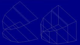
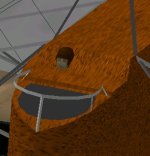
However, there´s a concavity (caused by a narrow rather vertical part) crossing the top surface of the nose and shows up as a transparent slit. I´m trying not to have to split the surface into 2 components, because the nose is already split into 2 components - one with the up/down surfaces and one with the 2 sides. (Blueprint screenshots shown).

I´ve tried sequencing the part in at the first position and also in the middle and at the end, but it´s always transparent, except when I put in the narrow vertical part separately into the .afa list, like in the screenshot of the nose of the model . (The pilot body is as yet not there).
Maybe I´m asking too much?

Cheers,
Aleatorylamp
 

Attachments

  • nose1.jpg
    nose1.jpg
    39.6 KB · Views: 0
  • nose2.jpg
    nose2.jpg
    19.2 KB · Views: 0
Hello Aleatorylamp,

I believe in this case, you are definitely asking too much from Aircraft Factory 99.

The idea of sequencing (perhaps there is a better term?) the Parts within a Component is to make them display in a certain order.
I know this works because I do this on a lot of projects, most recently on the P-40F Merlin Warhawk.

I believe in this case, it is a different problem.
When the sequence is wrong, you get bleeds, but the Parts do not become Transparent.
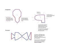
THAT happens when the Part is facing the wrong direction because only the side facing away from the Center of the Component is displayed.

Note that my second Component looks very much like the Orion Nacelle.
The opening of the lower Scoop did not display for the same reason.

Note that the example Structure has a bit of resemblance to the Spandau Machine Gun from my Eindecker.
This feature of Structures is how I could get away with a lot of strange shapes in a single Structure that would have required several Components.
(In reality I may have used more than one Structure but that was because they had to live in different Groups.)

Hope this makes sense.

I do wonder though, why not build your aeroplane's nose as a single Structure?
Is it because you need to texture it Top-Bottom as well as Left-Right?
If so, consider using Insignia Parts for Top and Bottom surfaces and Gluing in place.
I believe it is only slightly more expensive in Parts and saves on Components.

- Ivan.
 

Attachments

  • Component-vs-Structure.jpg
    Component-vs-Structure.jpg
    45.2 KB · Views: 2
Hello Ivan,
Thank you for your illustrating answer, and explanations! Your insight into the way AF99 works never ceases to amaze me. I´d always wondered what it was about structures that made them display better in certain circumstances.
I´ll follow your suggestion then, thanks! I had also been wondering whether to change the fuselage components to structures. I don´t know why I was still hesitating... The initial hollowed-out construction needed components there, but those are no longer necessary! As there are ample resources left, I´ll glue on textured panels for the top-bottom displays.
Cheers,
Aleatorylamp
 
My View of the World

Hello Aleatorylamp,

You're Welcome.

Although I didn't qualify it, what I explained is really my interpretation of how things work.
I don't really know for sure that I am correct but my theories seem to work well enough that I can make AF99 do what I want (mostly).
There are definitely a few holes in my "knowledge". For example, I don't know for sure how the "Center" of a Component is determined. I have a few ideas, but haven't taken the time to prove that the ideas are correct.

A lot of these ideas were gotten from examining the SCASM code that is generated from a AF99 Project and I can tell you that I still have problems doing a few things in SCASM.

- Ivan.
 
Hello Ivan,

Very interesting. I suppose the fact that it is possible to a certain extent to understand how the AF99 "insides" work, is what makes it attractive, and possibly easier to use than the higher complication of more modern programmes. I doubt the innards of Gmax or FSDS can be decyphered.

I always remember that in 2003 an FS2002 FD writer I knew said that it was a pity that AF99 was going to become obsolete, because having to use Gmax to build models was like using a sledgehammer to kill a fly...

BTW: with this comment I don´t want to criticize Gmax builders in any way - in fact I quite admire their pacience with the greater capacity for detail this programme allows. That goes for AD2k as well! I have never been able to get into them beyond the tutorials.

Cheers,
Aleatorylamp
 
Back
Top