Conspicuous by Their Absence

Hello Aleatorylamp,

I will have to disagree with you on this subject.

Perhaps the workings of Gmax and FSDS and AD2000 are more complicated and perhaps they are more difficult to understand, but they are also more full featured. I would much rather have the additional features because AF99 is definitely inadequate for building a really good project for CFS.

It is very much like comparing the relatively simple MS Paint to something like GIMP or Photoshop. One is simple and very easy to learn, but you run out of capability VERY quickly while the others may offer features you have no use for or take some experimentation to understand.

Basically I believe that killing a fly with a sledge hammer beats trying to kill a bull with a fly swatter. One results in a very dead fly and the other results in a very angry bull. Overkill is fine! Regarding your friend from 2003, AF99 is (unfortunately) no different today than it was back then. We push the limits a bit further these days because we have gotten smarter but we have lost no capabilities from what the program could do before.

This probably surprises you because you know I am still using AF99, but I have always believed it is an inadequate tool. That is why we keep having to use SCASM to do things that a really good 3D package SHOULD address. The reason I don't go full SCASM is because I prefer a visual design package to a coding package....

SO.... The conclusion from all of this is that although AF99 is a very mediocre tool, I believe it has enough features to do a pretty good looking visual model in many cases and its models CAN be corrected to work pretty well inside Combat Flight Simulator.

- Ivan.
 
Hello Ivan,

Understanding how the innards of anything work has always been a fascination for me. As a kid I systematically pulled apart toys to see how they worked, and eventually was also able to put them back together successfully. With AF99 it is still possible to act on some inner aspects specifically, SCASMing an AF99 creation, even though my gnat capacity is limited to visual cockpit corrections, and even here I need help flipping polygons.

Of course this tweaking business is not necessary any more in the more advanced a programmes - what could there be to tweak? It´s not possible anyway without being an expert hacker or a C++ wizard, so it was just a rhetorical comment.

I agree that the newer programmes can do much more despite being more complicated to use, and once I retire I might give them another try to see if my pacience can cope with them, although I do have my misgivings there. I´m probably just too lazy to work with them. There is something quite appealing in the rather more simple workings albeit more limited capacities and bugs of AF99, that makes me continue using it.

I was musing "what if Gmax and FSDS could make models for CFS1 - would that make a difference for me?", but the answer for me is clear - it wouldn´t, because otherwise I´d be using them already with CFS2 or 3 and FS2004 or FSX, ignoring CFS1 and FS98, which is not the case.

So for me it´s a matter of liking how AF99 works, made more interesting by the SCASM tweaking possibilities, even though I can only do very little. Also greatly enhancing the use of AF99 are your comments on its intricacies and hidden secrets. Fascinating, as they are not only lists of objective information, but mostly including reasoned deductions from speculative thought, leaving room for more speculation and experimentation!

Cheers,
Aleatorylamp
 
Last edited:
Concave wing structures

Hello Ivan,

I had made the Hansa Brandenburg G.1´s straight, rectangular wings, with structures because the hollowed out fuselage had eaten up so many components that there were none left for the wing. Then, being concave underneath, I made two structures for the main wing section, apart from separate ailerons and wing trailing edges.

Now, experimenting after your description of structures, I found that it is indeed possible to make the main wing section in only one structure - it DOES display as concave!

I thought this was very interesting - I had never tried this, taking for granted that concavities were "prohibited"!

Cheers,
Aleatorylamp

P.S. Of course, the nose and fuselage is coming along very well with structures, lined by top and bottom insignia surfaces textured separately. Perhaps I´ll use components for the wings later, as the shading looks better on component-made wings rather than structure made ones.
 
Hello Aleatorylamp,

I am glad things are working out for you.

I still can't do much with Structures in Wings because they don't allow tapered Wing Tips or Dihedral.
Both are generally show stoppers with modern aeroplanes.

I remember discussing some time back how I had put together the Spandau Machine Gun on the Eindecker.
I had thought it was kind of cool how with a single Structure I could build something that would take MANY Components.

Regarding AF99, my main complaint isn't that it is too simple.
My greatest complaint is that it is too linear.

Consider this:
The separation of various sections of a model can best be represented as a Tree Diagram.
As you go down a major branch, it separates into minor branches and each minor branch is further subdivided.
Having the ability to do this is essential because it is a pretty intuitive and logical way to define viewing planes.
With the right language definition, this can easily be coded in a simple text file.
This is how SCASM and other programming languages are designed.

The separation of the major Groups in AF99 are also done in a Tree representation, but within each group, the representation resembles a Vine more than a Tree. There are branches from the trunk but each branch only be separated from the trunk andthere can be no separations into smaller branches.

This is obviously easy to code but has great limitations. Sometimes it is necessary to spend some time to design a language to have certain features. I actually spent a week on a project just working on how to represent features that I wanted in a new language.
I don't see that this was done with AF99 and it is a shame because designing the language properly is certainly easier than the parts that the authors ACTUALLY DID DO.

It is a pity that there is not the opportunity to do a little fixing of AF99. With very few changes, it could be a much more powerful design tool.

- Ivan.
 
Happy New Year to all!

Hello Ivan,

...on the first day of the New Year, may it see a few new CFS1 models here!

So as I see it, this is what must have happened: In the days of BAO Flightshop (AF5), its "vine" tree, producing simple aircraft, was just about what the average user´s computer could cope with - the 1st bifurcation was enough! When it was upgraded to AF99, the average computer had become faster, but was underestimated. The upgrade included mainly only a bigger file size and higher parts count but not a "Tree" tree with 2nd or 3rd bifurcations.

Your "Vine" rather than "Tree" illustration/explanation expands upon your older glue sequence description for the parts comprising an example tail: fin, glue, aft-fuselage, glue, left tailplane, glue, right tailplane.

Being a vine, there´s no room to glue on rudders or elevators - each piece of glue represents a bifurcation, and a sequence including these in the respective positions won´t work.

I suppose the grouping principle tail, tail left/right, tail upper, tail upper left/right, was an effort to remedy this, but made it more complicated and less effective than a "Tree" tree would have been. A pity, becuse it would have been nice...

Cheers,
Aleatorylamp
 
Happy New Year, Everyone!


Your "Vine" rather than "Tree" illustration/explanation expands upon your older glue sequence description for the parts comprising an example tail: fin, glue, aft-fuselage, glue, left tailplane, glue, right tailplane.

Being a vine, there´s no room to glue on rudders or elevators - each piece of glue represents a bifurcation, and a sequence including these in the respective positions won´t work.

Hello Aleatorylamp.

I had already typed a fairly long reply that just vanished a few seconds ago.... Hopefully I won't miss anything serious on the second attempt.

I believe your summary of my Vine / Tree / Glue explanation is pretty good.
The problem though is that although the "bifurcation" of the Tailplane into a Stab and Elevator cannot be specified in AF99, its single direction assembly sequence and simple rules it follows make it impossible to build the proper sequence.
This is why I don't really try to build animated control surfaces.

I believe in another aspect, you are confusing the complexity of the modelling application with the complexity and size of the model being created.
AF99's assembly sequence does NOT result in a particularly economical MDL file. This can be seen by examining the SCASM code from a disassembled MDL. AF99 adds viewing planes for EVERYTHING whether they are specified or not. The problem is that although the viewing plane / Glue code exists in the MDL, the author cannot specify where it is located and AF99 does a rather poor job of guessing where it should be.

Additional complexity in the modelling application would not result in a lot of additional code because most of the complexity would really be in the DESIGN of the application. As a negative, the resulting program would certainly be a bit more complicated to use. The current AF99 assembly process has no concept of subroutines and the new assembly process would need to implement something equivalent to a subroutine.
The resulting program would certainly be no more complex than other Integrated Development Environments or Compilers.

Regarding the question of whether computers of the era were capable of handling the more complex models, consider that the computer I am currently using for development has not been significantly modified since I built it in 1997.

- Ivan.
 
Hello Ivan,
It is frustrating how the window times out and one can´t post when one finishes writing, and then the text gets lost. Sometimes I can go back to the writing window, copy the text I´ve written, open another Internet window, loggin SOH anew, go to the thread, open the posting window, paste the text and post it!

I was just speculating on a logical reason for the simple Vine tree style without subroutines implemented when AF5 came out in 1997, which was not upgraded to a Tree tree for AF99 in 1999.

So it wasn´t the average computer performance that was the limiting factor. The Pentium 233 MMX came out in 1993, so by the time 1997 came along it, must have come down in price pretty much so as to be a computer for the average user, perfectly capable of producing more complicated models to be made properly with a Tree tree style programme with subroutines.

It must have been that the creators of the programme did not expect modellers to create more complicated models. I could also be wicked and come to think they didn´t know how to programme something non-linear. It is curious that animated surfaces were not catered for either, until Aircraft Animator came out later, to do what it could with what there was. AF5/AF99 wasn´t meant to make animated surfaces anyway!

I suppose I keep coming back to the subject in the subconscious hope of finding solutions to the unsolvable limitations created by our Vine-tree.

Cheers,
Aleatorylamp
 
Hello Aleatorylamp,

Recommendations for Combat Flight Simulator were for a 150 MHz Pentium with 3D graphics card as minimum.

My computer actually started life as a Cyrix 686 P200+
The memory bus speed was 75 MHz and the processor ran at 2x.
Even at 150 MHz, this system was quite fast but the Cyrix chip although it was probably as fast or faster than a Pentium 200, it was more instruction compatible with a 80486 and would hang on some Pentium instructions.

The Pentium 233 MMX is actually faster compared to a Pentium 200 than its clock rate would indicate; There were improvements besides the MMX additions.

When I replaced the processor, I had a choice of either going with 75 MHz bus and 3x processor for 225 MHz or 66 MHz bus with 3.5x processor for 233 MHz. I chose 233 MHz because it was a bit more conventional.
I also found that I could enable three of the four banks of 64K of memory. One bank was shared between the two memory types, so I could not populate both.
I also had to cut away parts of the interior of the case to install the extra bank of memory.

Regarding the Vine versus Tree arrangement, keep in mind that it only meant that the design application could be simpler.
It didn't mean the resulting model is shorter or simpler. In fact the model is likely to be more complicated.
Although the design application is simpler, it doesn't mean that it requires any less processing power.
I believe the developers of the design application just took a simpler and easier way out because they didn't expect models to get very elaborate.

Pity they didn't do it. It would have resulted in a much nicer generation of models though one cannot guarantee that result.
Consider that even with the Vine assembly limitations, we can build pretty good models with minimal bleeds today but that most of the past designers using AF99 never figured out how to do it.

The 30 Components and 30 Structures limitation was probably also for the same reason. 40 Components and 20 Structures would have made more sense.
Who would have thought we would be trying such fancy things a few years down the road?
Who would have thought AF99 would still be in use this many years later?
Note also that the original non-patched AF99 would only handle 800 Parts in all and the Wizard did not work at all from what I could tell.
The animation was clearly an afterthought, thus the "Speed Below" tags to communicate with Aircraft Animator.

Of course there are solutions to the Vine versus Tree: Work in SCASM!

- Ivan.
 
Structures are beautiful - further structure study

Hello Ivan,
Interesting, the way you built up and upgraded your computer!
I definitely agree that in spite of its shortcomings, the fact that work-arounds can be found in AF99, is quite amazing. That is the good side of the whole story, and my experiments in the last few days only illustrate this further, with my Hansa Brandenburg G.1 side-track from the P3-Orion.

Your explanatory diagram about structures and components, and your single-structure machinegun on the Eindecker have spurred some investigation on my part.


Something made with a component cannot display concavities and needs more than one component. I had always thought this applied to structures too, but as you said, it doesn´t, as they use a different display
system.

The first experiment involved the Schwarzlose machine guns on the Hansa B. I had them in two structures, barrel and body, out of habit, to avoid concavities. However, this played hell with the glue-sequencing of gunner,gun, gun-ring halves and gunner-well circle, and as soon as I made one-structure MG´s, everything seemed to click into place! They can now even be textured.


This was a small victory compared to the second experiment:


I had always made concave wings with three separate sections (forward, mid and aft). The sections had to be 3 components if the wing was tapered, but for reactangular wings I liked using structures (they save work). In the case of components, there is no other way of displaying the concavity, but with structures, contrary to what I´d always thought, there is no need for dividing the wing up, not even for the aileron cut-out! (my obsession with moving parts!).


Here I always had a separate structure for the wing trailing-edge next to the aileron, but this invariably creates hairline cracks at the joint, impossible to eliminate even by adding little flanges to the structure ends (they reduce the size of the hairline cracks but create interfering darker lines). Then, ailerons, if rectangular, can also be structures, but not in the case of the Hansa B., because the aileron trailing edges slant backwards as they go out.


This causes an added complication even if one were to eliminate moving parts. The shape of the top wing needs a component inserted for the ailerons, as the shape is no longer rectangular.


So here, on the Hansa B., I carved out the aileron hole, similarly to how I carved out the complicated fin/rudder structures on the Fledgling. Now the wing is one whole single structure with ailerons, and there are no hairline cracks.


Finally, there is a glue piece gluing the aileron to the wing because the aileron cut-out cannot be made exactly perpendicular, and has to have a difference of 0.01 ft in the hinge line ends (this is for the two bulkheads the structure needs here), and this makes a wall what bleeds through the aileron if it is not glued.


Here are a few screenshots to illustrate the point. I really like the smooth curvature of the wings.


Cheers,

Aleatorylamp
 

Attachments

  • Hansa1.jpg
    Hansa1.jpg
    61 KB · Views: 0
  • Hansa3.jpg
    Hansa3.jpg
    106.4 KB · Views: 0
Triple rudder

Hi Ivan,
The glue sequence on the tail empenage is also strange here, and quite successful.

The triple rudder adds difficulty to the simpler bleedthrough-avoiding glue sequence involving no moving parts, so the problems caused by the triple rudder could not even be solved by eliminating animations.

Strangely, the tailplane is one piece, glued onto the fueslage tail section, which is a component without a lid, as the tailplane covers that, and a one-piece elevator is glued to the tailplane. Then the fin and all the rudders are in tail-upper with the wires, and the backward-slanting outer-rudder struts are in tail upper left/right. An unexpected setup, but it works better than any combination of left and tight tailplane and elevator halves grouped or glued anywhere else, possibly because the tailplane sits on the fuselage as opposed to being fixed to the sides... although I did have to eliminate two wires going from the tailplane edges to the fuselage on both sides underneath - there was no way of eliminating those wire-bleeds through the tailplane.

There is a little bleed as yet with the external rudder struts, but I don´t know if I can get rid of that. Them, the texture on the central fin/rudder needs improving as it diffuses where it meets the taiplane.

Maybe I can upload this quite soon if things don´t get too complicated - and then I can return the hammers to the P3-Orion panel-beaters for them to finish the nacelles!

Cheers,
Aleatorylamp
 
Almost ready

Hello all, Hello Ivan,

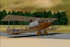
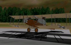
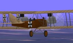
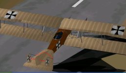
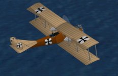
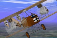
I´ve been busy with the new CFS1 old 1916 biplane, and it´s almost ready.
It´s quite an important model historically as it was Ernst Heinkel´s first attempt at a twin-engined biplane bomber, with 2x160 Hp engines on outriggers instead of on the wings. It was apparently OK for the prototype with Maybach engines, which ran smoothly, but the German Military didn´t approve so he had the model made in Austria with Austro-Daimler engines which vibrated quite a lot. 39 were built and only saw one bombing mission, and were then used as trainers for the new Gothas which were coming out. They also tested it with a Skoda anti-tank cannon in the nose, which was shortened for CoG reasons, probably, and that must have had quite a punch. That would make an interesting variant for this model.

The triple-fin tail, 3 crew and 2 machineguns went surprisingly well with able glue sequencing, so it is quite satisfying, ...obviously thanks to Ivan´s patient coaching!
There´s still a black cabin well part bleeding through the fuselage, but hopefully I´ll have that licked soon and I´ll be able to upload it tomorrow or the day after.

The Spanish celebrate Christmas on the 6th January, the 3 King´s day, so it could qualify as a Spanish Christmas present!
Here´s some screenshots meanwhile!
Cheers,
Aleatorylamp
 

Attachments

  • Preview1.jpg
    Preview1.jpg
    64.6 KB · Views: 0
  • Preview3.jpg
    Preview3.jpg
    54.4 KB · Views: 0
  • Preview5.jpg
    Preview5.jpg
    52.5 KB · Views: 0
Hello Aleatorylamp,

I believe there is a better solution to your tail assembly sequence.....

Consider putting all the pieces into the Tail Group but Start with the Central Fin.
Sequence it as follows:

Center Fin
Center Rudder
Starboard Rudder
Port Rudder
Starboard Fin
Port Fin
Horizontal Stabiliser
Elevator
Tail Cone

The locations of Glue should be pretty obvious with this sequence.
I believe the result should be pretty close to zero bleeds without the complication of two separate Groups.

Regarding the Wing as a Concave Structure.....
It IS possible to make a Concave Component; That was the whole point of the earlier discussion.
Just start with the middle of the underside of the Wing and move forward and aft from there.

If you MUST go with Structures and have an issue with the Aileron Cutout, consider re-shaping the Aileron to match the cutout.

- Ivan.
 
Cup of tea?

Hello No Dice,
Glad you like it! Thank you for your moral support!
Have a virtual cup of tea here in the sub-sub basement!!
I like Lapsang Souchong, but we also have Earl Grey or Irish Breakfast...

Hello Ivan,
Thank you very much for your indications! (cup of tea, maybe Darjeeling?)

For the moment actually, the Tail-upper group seems to solve my problems rather than to create them, as opposed to tail-upper left/right and tail-left-right that only worsens them. It is working perfectly!

But I had to take out most of the wires. I have marked them in red in two screenshots.
The only wires that are allowed at the moment go from the upper side-rudder tips to the central rudder base.
Left and right fins in this case are of course the slanted rudder struts that hold them up.

Your list brings memories of the two Fledgling pilot glue-dancing act... with two slanting glue pieces, perhaps - between Port Rudder and Starboard Fin, and Starboard Fin and Port Fin?
Also, I suppose a tail skid can be glued under the tail cone.

So in your list, glue template separators following each part could be:

Center Fin + vertical front/back
Center Rudder + vertical right sideways
Starboard Rudder + vertical left sideways
Port Rudder >>> + a slanted glue piece <<< ?
Starboard Fin >>> + a slanted glue piece <<< ?
Port Fin + horizontal up/down
Horizontal Stabiliser + vertical backwards
Elevator + horizontal up/down
Tail Cone >>> + horizontal up/down <<< ?
Tail Skid

Would this setup also allow the missing wires? The only one that could work well at the mmoment is the left upper slanted one. For some odd reason the right upper slanted one disappeard when viewed from the side-front. The horizontal upper ones bleed through the central and lateral rudders, and the lower ones always bleed through the tailplane.

Ailerons are fitted into the Aileron cut-out on the wing structures - that went ok, and fit quite nicely the hinge slant is offset 0.01 ft from the perpendicular.

Thanks for the description of the part-order in a concave single-component wing! I hadn´t expected that could be done!

The wings are structures (with 1 degree dihedral >ughh!<), as I have no components left. They went into things like left/right gunner rings, lateral rudder struts, tail skid, landing gear struts, radiators, and the central fin/rudder, Parts count is squeezing at 1178. Then, the central fuselage has a cross section of a trapeze mounted on a square, and I needed several components to separate pilot and gunner wells because of the black insignia piece glued to the top of each, and there is a slanted step in the middle of the well.

Update: I´ve fixed the pilot well bleedthrough, and then changed the central fin/tail to structures again, so now I have 2 components for the top wings - to improve the shading there (aileron components always cause shading mismatch in wing structures). That way I can also experiment making a concave wing-component! Parts count has now gone up to 1196 (149.5%) but will go down again with the wings as components - it should save possibly 3% (24 parts).

Let´s see... Sorry about the long post, but sometimes these happen...
Cheers,
Aleatorylamp
 

Attachments

  • Tail ensemble.jpg
    Tail ensemble.jpg
    53 KB · Views: 0
Last edited:
wing Component build order

Hello again, Ivan!

The top wing component is made of 7 upper and 7 lower strips making upper and lower surfaces.
The outer rim is vertical and has 7 segments as well.
As you said, numbering from the inside and going forwards and backwards, alternating upper and lower segments of the surface we´d have, leading edge on the left:

wing tip pieces: 11t 7t 3t 1t 5t 9t 13t
upper surface p: 11 7 3 1 5 9 13
lower surface p: 12 8 4 2 6 10 14

Updated correction:
------------------
I tried this build order:


1t, 1, 2, 3t, 3, 4, 5t, 5, 6, 7t, 7, 8, 9t, 9, 10, 11t, 11, 12, 13t, 13, 14.

...but it won´t work - the undersurface stays invisible. Maybe I shouldn´t have alternated the top and bottom parts as I went forward and backwards from the middle?
So perhaps, the component-parts should be grouped as per their surface, the top parts first in the list, the tip parts second and the undersurface parts last?

2nd Update:
-----------
No, sorry this didn´t work either. OOoooppssss!!!! I didn´t pay attention! I should have started with the with the underside! .... NO, no, that didn´t work either.
I´ve just done it, working forwards and backwards starting from the middle, underside first, then top surface, and lastly the vertical wintip pieces.
I must be doing something quite wrong, but I don´t know what it is.

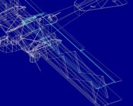
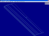
The blueprint screenshot shows topwing component in blue lines and aileron component in light grey (its outer end makes the wing wider at the wingtip). Parts count is down to 143.3% (1146 parts) and the wing component itself is down to 19 parts from 34, and there are still 3 structures left!!

Thank you for your inspection and possible suggestions!

Cheers,
Aleatorylamp
 

Attachments

  • topwing component.jpg
    topwing component.jpg
    50.7 KB · Views: 0
Last edited:
Hello Aleatorylamp,

Actually my preference would be Earl Grey. I drink it all the time (decaf though).

Regarding the ordering of the Wing Parts.
First thing to check is that the center of the Component will end up in the correct location.
To do that, just add all the Parts and don't worry about the order.
If you see bleeds, that is fine, but if you see transparencies, then you know the shape of the wing is not workable as a single Component no matter what the order of Parts is.

Now assuming that you don't see transparencies, you need to add all the Concave Parts first.
I usually start with the deepest concavity and work outwards. (This is only a general rule, sometimes things are different.)
In the case of your Wing:
2-4-6-8-10-14-12 assuming that the Parts are numbered from Front to Rear....
Then add all the non-concave parts because order does not matter there.

So... Only the Concave stuff matters and it must be listed first.

To make it more clear:
If the lower surface of your Wing has 7 Parts numbered 1-2-3-4-5-6-7 from Leading to Trailing Edge:
4-3-5-6-7-2-1
or something similar....
The order does not alternate because I believe the maximum Concavity is slightly ahead of mid-Chord
AND
because the Trailing Edge continues its concave curve while the Leading Edge reverses as it gets to the first Part.

I can't see the exact shape from your screenshot but that is my best guess.

Hope that helps.
- Ivan.
 
Last edited:
Hi Ivan,
Thanks for your coaching on this! You are very kind.

Your explanation is quite clear, and the numbering too - you understood mine and I understood yours.
There is a numbered side-view screenshot below, just for clarity´s sake, showing the top and bottom parts and their numbers.

So... I´m afraid that in this case the entire wing underside IS transparent, so it´s a definite no-go then. ...Possibly the concavity is too pronounced.

Anyway, the wing as a structure does look beautiful, with only a small shading difference between ailerons and leading edges, which is negligible, I´d say, so I´ll go ahead with that.

Then, other than taking out some wires from the tail, everything shows correctly, so there´s no real problem there either. With effective "Ivan´s-Konga" type Sequencing for the forward gunner´s well and the 3 separated sections of the shared oval rear well for rear gunner and pilot has yielded nice results there too.

Instead of texturing the guns, which are all grey in reality anyway, I used the last texture to put a "Hoheitszeichen", meaning "Highness Mark", the German for the Maltese Cross, on the nose-tip, as some units had that - I hadn´t discovered it until now, as when I made the model, a few years back, there were not so many photos available.
So, I´ve got the Dp file done, and I´ll SCASM it for the V-Cockpit now.
Well, it is just in time today for the Spanish Christmas - the 3 King´s Day !!

The Cannon Version info is also new. I think I´ll also provide a snub-nose variant with the Skoda anti-tank puncher! That has the forward gunner´s well a bit further back. That should be useful for CFS1 fighter-simmers to shoot up tanks, and ought to please more than one!

However, first I´ll finish the P3 Orion, which is meeowing in the corner stretching its paw forward like our cat.

Cheers,
Aleatorylamp
 

Attachments

  • Screenshot-6.jpg
    Screenshot-6.jpg
    29.8 KB · Views: 0
  • Screenshot-3.jpg
    Screenshot-3.jpg
    46.7 KB · Views: 0
Merry 3 Kings´Day!

Hello all!
I wish you all a very merry Spanish Christmas 3-Kings´ Day.

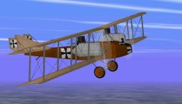
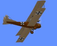
As promised (just on time ha ha!), I´m pleased to say that there´s a new golden oldie from 1916 in the SOH Warbirds CFS1 Library: The twin-engined Hansa Brandenburg G.1 bomber-trainer, which has turned out quite nicely with very few bleeds, and a CFS1 .air file, SCASM-corrected V-cockpit, Dp files.

http://www.sim-outhouse.com/sohforum...id=19&id=20699

Thank you Ivan, for your continued support!

I have also uploaded the latest FS98/CFS1 USAF Starfighter TF-104G, into the SOH Warbirds Library. It has great textures by Udo Entenmann, for the event that there is a little interest for this "space rocket". This is an extensive upgrade for FS98 + CFS1 re-work of a BAO Flightshop AFX of a RG-104G single-seater Starfighter for FS5.

Here´s the link to the Starfighter two-seater:

http://www.sim-outhouse.com/sohforum...id=19&id=20702

Enjoy!

Cheers,
Aleatorylamp
 

Attachments

  • TF-104G-Teaser-B.jpg
    TF-104G-Teaser-B.jpg
    42.7 KB · Views: 0
  • -Screenshot3.jpg
    -Screenshot3.jpg
    83.6 KB · Views: 0
Last edited:
question??

dear Ivan....
what does bifurcation mean?
also bear in mind that an af99 afx is able to be
interpreted by af2000___so could you use it to add features?
***
many yonks ago I built a simple plane at Meigs
beside the runway__this was before I understood
vectorjumps
>>>papingo
 
Hello Papingo,

You really should be asking Aleatorylamp. He used the word first.

Bifurcation just means a split into two parts.....

Yes, I know you can import an AFX into AD2000. I may do that eventually with projects that are really too big for AF99.
The problem with doing it now is that I don't know how to use AD2000 yet. I will get there in time unless time gets to me first.

What kind of aeroplane did you build at Meigs? Any possibility of bringing it into Combat Flight Simulator?

- Ivan.
 
Back
Top