• Guest Please check out the Help Wanted thread in Ickie's NewsHawks.
    The future of the Outhouse depends on you!
    Help Wanted

Gmax Video Tutorial Series - Beginning Modeler

Hi Milton,

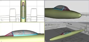
So it may take me a while, but I am on my way now, thanks to you! Watched all 47 videos, figured out how to make an exterior node/part, and centered that at 0,0,0. Also centered my calibration backgrounds and aircraft there, at a reasonable 1/4 MAC location, and started rebuilding the aircraft from scratch. Rebuilt the fuselage, and got a rear canopy part completed that I am very happy with after trying a number of approaches this weekend.

The attached picture shows where I am so far. The red aircraft is the before tutorial version, the blue is the after tutorial version. :)

Thanks again.

Best regards,
Melo

Melo,

Ah, that's great progress. The important thing now is that you have the confidence to go through the processes without stumbling too much with the tools. I would say that you are on your way to accomplishment. Take your time, enjoy the process. :applause:
 
Hi Milton,

Working on my front canopy frame now. Your method to start it on the fuselage and build up from there worked great!

Two quick questions though. I have cut out some rear canopy windows with no problems using boolean, but how do I get the transparent texture to display on them?

The second one is a Gmax settings question. You use the transform type in by right clicking on a move or uniform scale etc. to nudge verticies or parts in your videos. But my transform type ins are set to absolute world and each click moves or scales the part a large distance. Can you point out how or where to change the transform type in setting to absolute local?

Thanks again! Have tomorrow off, so a long weekend to get some detailed designing done. :)

Best regards,
Melo


RE: Glass: I usually just change those parts to transparent (like when you are building against a 3-view) until I get around to mapping things.

However, when you get around to mapping the glass, there are two options for windows.
I use both depending on the situation.

For general glass without any fancy stuff in the alpha channels, I use a general dark gray with a dark alpha channel in the sim. (Just any gray 24 bit for gmax UVW folder.)

1) Most of my glass, I just select and map them together and apply a glass_t.bmp texture to them. The purpose of this technique using an _T.bmp, is that it allows you to add glossiness on the windows (with the alpha channel) and I add material specular settings (sun glare if you will) of 50. The material properties then must control all the opacity/transparency. For that I use opacity settings of 6-7%. The alpha channel controls the glassiness in the sim. The glass appears transparent in gmax.

2) For windows where you might want to add some special treatment (reflections of the interior or fog around the edges), use glass.bmp (no_T). Opacity = 99%, specular = 50%.
This requires you to use the alpha channel for transparency. Because of this, you can add special effects in the alpha channel that will show up in the glass in the sim. In gmax, the glass will be opaque.

RE: Right clicking Scale or other modifying icons:

After you have selected the vertices (or whatever sub-object), select the tool you want to use, then right click the icon.
Then select the Local Coordinate system changing it to Local.
 
Hi Milton,

Thanks a lot for the detailed explanation about glass textures. Very clear. (no pun intended)

And thanks for the coordinate system explanation, that one was driving me nuts.

Best regards,
Melo
 
Hi Milton,

Is there a trick or procedure to add (create) polygons easily? I am working on the front canopy and trying to add polygons as you did, but most of the time the polygons I am creating either have an invalid face and fail, or I think I am creating the polygon just where it belongs in one view, but when I look in the other views, the far end of the polygon is no where near the attach points I am trying to connect to. Then trying to manually move it back into the correct position is very difficult.

For now trying a different tack and method to finish the front canopy. Part of the problem, that I probably caused, is that the canopy frame I made on the fuselage was too complex. (Too many vertices) Going back to one of my previous saves to rework.

Best regards,
Melo

If trying to create a poly when you do not have 4 vertices to attach to, then create a 3-sided poly.
Then go to edge sub-object mode, select the long edge you need a vertice from then use the DIVIDE in the command panel roll-out.
That creates a break in the line adding a vertice.
Then just move that vertice into place.

If you have 4 vertices to attach a new poly to, then ensure you are creating that poly in a counter-clockwise fashion, and just like in golf, do not take your eyes off the Cross until you click, otherwise you will add an isolated vertex.
If that happens, (you can Undo twice-once for the poly created and once for the add vertex), or in vertex sub-object mode, go down the command panel and find "Remove Isolated Vertices".
 
Last edited:
Thanks for the detailed advice. I will do some practice sessions building polys until I get the hang of it.

Best regards,
Melo
 
Hi Milton,

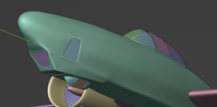
So I ended up building canopy parts over and over again using different strategies, but all good practice so no wasted effort. I am happy with the results so far. :)

Starting to really get the hang of it now. Could not have gotten this far without your excellent advice, so thanks again!

Here is a picture of my progress.

Best regards,
Melo

attachment.php
 

Attachments

  • Meteor PR-19a.jpg
    Meteor PR-19a.jpg
    41.7 KB · Views: 146
Hi Milton, thanks a lot, music to my ears! Now on to add details and camera pods to the fuselage. :)

About a month ago, I also took a lot of landing gear pictures of the only public easily viewable Meteor Jet in the USA. Luckily Chino is not too far of a drive from home, so it was a great research trip. That will be invaluable when I get to the landing gear phase.

Best regards,
Melo
 
Hi Milton,

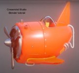
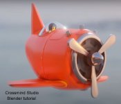
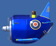
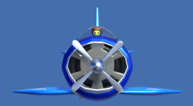
I'm back. Took some time away from modeling for a variety of reasons. Now I am happily retired and have the time to get this project done. In the process I have switched from GMax to Blender. I finished a Crossmind Studios youtube 7 part video course and have produced an aircraft in Blender based on their tutorial aircraft. See the attached pictures. I'm sure I will be referring back to your Vultee XP-54 Swoose Goose video series a lot in the process of building my next aircraft. Thanks again for the videos and your encouragement for beginning modelers!

Best regards,
Melo

tutorial aircraft 2.JPGtutorial aircraft 1.JPGtop view.PNGright view.PNGfront view.PNG
 
Hi Milton,

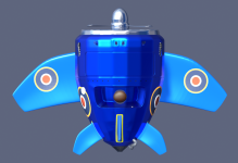
I am making good and steady progress now. Thanks for all of your tutorials and advice. Much appreciated!

Best regards,
Melo
 

Attachments

  • aircraft progress.PNG
    aircraft progress.PNG
    99.5 KB · Views: 47
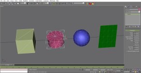
I am just beginning my gmax education thanks these great videos. The faces of my objects have diagonal lines across them which is different from the tutorial examples -- how do you switch those off?
 
I am just beginning my gmax education thanks these great videos. The faces of my objects have diagonal lines across them which is different from the tutorial examples -- how do you switch those off?

Hi WesCov,

Happy that the tutes are helpful.

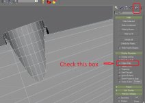
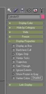
In Gmax, in the Control Panel top right, look down to Display Properties, Check the Box show in the attachment.
 

Attachments

  • -2024-mar-30-002.jpg
    -2024-mar-30-002.jpg
    154.3 KB · Views: 19
Thank you both. I see the checkbox and I see the CTRL-E change the option but neither actually takes off the diagonals on the object. Is there some overriding option I could have set inadvertently?
 
Thank you both. I see the checkbox and I see the CTRL-E change the option but neither actually takes off the diagonals on the object. Is there some overriding option I could have set inadvertently?

Make it easier for us to help by posting a screenshot of what you are seeing (like I did above). Include the Display Properties like I did.
Also show the Command Panel Modifications you have like Editable Mesh, or Editable Poly so we know what we kind of object we are looking at and how it's been modified.

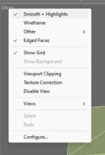
Upper left in your window (where it usually displays Left, Right, Top, etc) right click to see what VIEW settings are active.
 
Thank you! The attached screen shots show the object parameters, the viewport settings, and the object display parameters.
 

Attachments

  • Object Parameters.jpg
    Object Parameters.jpg
    120.2 KB · Views: 4
  • View Settings.jpg
    View Settings.jpg
    15.4 KB · Views: 1
  • Display Properties.jpg
    Display Properties.jpg
    17.3 KB · Views: 3
Click on each object in turn and turn the diagonal lines off (or on, if you wish) with Control-E. You've also got the bounding box showing around Cylinder01 – the outline showing the overall maximum size of the selected object – which can be handy, or can be a nuisance at times. J turns it on or off.
 
Click on each object in turn and turn the diagonal lines off (or on, if you wish) with Control-E. You've also got the bounding box showing around Cylinder01 – the outline showing the overall maximum size of the selected object – which can be handy, or can be a nuisance at times. J turns it on or off.

Thanks Tom for your help. I have forgotten half of what I knew on Gmax after so long away.
 
Back
Top