Lockheed Electra Model 10

Wing profile shape?

Hello Smilo, hello all!
Making the wingroot, I discovered that there were some adjustments to be made at the bottom of the central-fuselage bulkheads, in order to get correct shapes for the wing-root trailing edge and the fuselage sides. The rudimentaruy central bulkhead drawing had the floor too "V"-shaped.

Now, to make the wingroot, AD2K basically offers 2 useful options for the wing profile, both of which are acceptable despite their shortcomings, but none of which offer the exact shape required. Now the problem is to decide which!

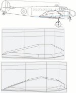
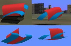
The top of the picture shows the required wing-root shape in red: Bi-convex, with a positive angle of incidence.

Below that are the two AD2K possibilities:
The bi-convex profile leaves the trailing edge too high and the simple plano-convex profile leaves the trailing edge too low.

So, what shall it be? We could always have a vote...

Incidentally, what is a really very cool building option offered in AD2k is the "Intersection", typically used for wing-fuselage joints:
Instead of placing the inside inner-wing profile template flush with the fuselage wall (which can be difficult if curved) and then cover the space upto the outer profile template with panels, the Intersection Option is more automatic: It uses an inner profile template placed within the fuselage, and then covers only the outside surfaces going towards the outer profile template. Very practical!

Cheers,
Aleatorylamp
 

Attachments

  • whichwing.jpg
    whichwing.jpg
    42.1 KB · Views: 5
and now, you've come to an ad2k weak point,
the cord profile options are less than adequate.
but, that's just my opinion and i'm being nice.
so, to answer your question,
as always, in the end, it's your call.
my vote would be neither.
take the time to create your own template.
you'll be much happier with the results.
 
Hello Smilo,
Yes, the pre-fabricated profiles DO seem to be a bit obnoxious. Apart from there only being 3 basic profiles to choose from, even these are very difficult to define, and the front section almost never comes out as defined anyway.

Then I had an idea, to manually alter the shape of a section made with pre-fab profiles by moving some vetices, eliminating some parts and adding some new parts - a bit labourious, but easier than making the whole section by hand, piece by piece.

But now you mention creating your own templates to build a section, so it sounds like there´s an option to convert a manually drawn chain into a template. This would of course be even easier!

Let´s see what I can find!


Update: OK, I´ve made two chains with the shape I want for the inner wing: One for the inner wing root template to go inside the fuselage, and one for the outside template to go inside what will be the engine nacelle.
BUT: I haven´t found an option to turn the chains into templates. Possibly there isn´t one, and consequently, will all surface panels have to be made by hand?

If so, all vertices will have to be aligned by hand with fuselage and engine nacelle bodies, lamentably without being able to use the "Intersection" option.
In this case, an easier solution to arrive at the desired wing profile would possibly be manually altering the shape of an existing inner-wing section made with the simple pre-fabricated wing profile.

What do you think?


Cheers
Aleatorylamp
 
Last edited:
i have errands and a doctor appointment today.
so, i'll look into it when i get a chance.

quick question, how many vertices
make up your chord chain?
as i recall, template shapes can be changed
using the template creator.
then, resized and covered.
 
Hello Smilo,
Good luck at the doctor´s!
Thanks! There are 11 vertices in my chord chain.
I´ll try and see if I can find the options you mention in the template creator.

So: The options in Ad2K don´t give you more than 6, 7 or 8 points, and I can´t find how this can be increased.
Then, I looked into Ad2K2, and here you are allowed 3 more options: 9, 10 and 11 points - but that´s AD2k2, and making an 11-sided template with that, won´t load into AD2K, I´m afraid.

Cheers,
Aleatorylamp
 
thanks Stephan, i'm heading out shortly.

try this...start with a 12 sided circle,
stretch and pull the vertices
into the desired positions.
maybe, over simplified,
but, you get the point, right?
 
Success of sorts

Hello Smilo,
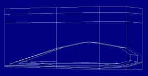
Getting into the wingroot sub-assembly parts with the Draw - Edit Chain menu, I managed to alter the shape of the wing-root by pulling up the trailing-edge vertices. The originally plano-convex wingroot, made with 8-sided simple profiles, is still a bit flat at the bottom, but the shape seems to be getting closer to what I want.

Maybe the next step would be to cut out a bottom middle section to make the bottom surface convex too, so that the sloping angle upwards to the trailing edge starts further aft.


In the screenshot you can see the original templates in blue (horizontal blue base lines), and the white lines are at newly positioned angles giving a higher trailing edge. Possibly this is partially what you were referring to editing the shape before, but it isn´t really the template that has been edited.

Regarding the 12-sided circle you mention for forming a template into a desired shape: I would have expected that kind of template to be for a fuselage bulkhead, so it would be at 90 degrees to the wingroot cross-section profile type template I need... ...but I´ll try it out anyway!

Cheers,
Aleatorylamp
 

Attachments

  • Bent.jpg
    Bent.jpg
    29.4 KB · Views: 1
Better, for the moment

Hello Smilo, hello folks,
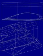
The wingroot now has the desired bi-convex shape, with bottom surface less curved than the top.
The only way to do it was to manually edit the sub-assembly itself, moving vertices and adding panels.

But... the kicker is, it won´t compile - I hadn´t tried that yet, and previous versions won´t compile
either, so at least, the flaw is not in the wingroot shape-improvement itself, which is a relief.
Stupid... I forgot about changing all the polygons in the listings because they don´t have textures yet...
that´s why it won´t compile yet!

Cheers,

Aleatorylamp
 

Attachments

  • better.jpg
    better.jpg
    53.6 KB · Views: 1
have spent the past few hours
fiddling around with templates.
basically, trying to remember.
as i recall, i said the hell with it.
i don't have the time for the aggravation.
first off, section temples can be made
to be viewable from different planes.
click on the radio buttons at the top
and select x0y, y0z or x0z
to get a top, front or side view.
unfortunately,
template configuration is very limited.
too bad there is not a random option
which would enable one to place
vertices wherever desired.
as you've discovered,
the wing profile options are also lacking.

just for fun, i drew an 11 point chord shaped chain.
next, i clicked the 'build a cylinder' option
using said chord chain.
after is was built,
i 'enlarged' the original 'template' chain by .25%
i now have a tapered cylinder
that looks a lot like a wing.
as an added bonus,
there are two vertices
forward of the trailing edge.
one upper and one lower
that will align with the aileron and flap joints.
 
Hello Smilo,
Thanks for the instructions, and I appreciate the effort that went into discovering how it works. I´ll use the idea!
I was under the impression that the cylinder option would force the use of the same profile at both ends, but obviously this wouldn´t make much sense.

For the moment, I´ve obtained a wing-root by using an 8-sided profile, modifying the sub-assembly by adding 1 side underneath and pulling up the trailing edge slightly. It´s still only only 9-sided though, but it works.

However, adding further sides to improve the shape will be more laborious than using your idea to build a new 11 or 12 sided profile-chain, and making a tapered "cylinder" with it. This will also be a much easier way to make the outer wing.

I´ve also managed the sequencing for the two wingroots and the central fuselage - it wasn´t complicated (this time...).

Thanks again for the solution!

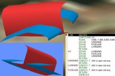
Update: The way to build a nicely shaped 11-sided inner wing works very well.
The only difficulty is that the intersection option does not apply here, and it appears that vertices will have to be lined up manually with the fuselage and the engine nacelles. Nothing is perfect in this life!

Cheers,
Aleatorylamp
 

Attachments

  • works1.jpg
    works1.jpg
    41.7 KB · Views: 2
Last edited:
yes, it's true, this is not a perfect solution.
if you've tried it, you've seen
the new cylinder end is a duplicate configuration
of the original chain, (minus the chain)
with the vertices tied together.
the cool thing is, if you want,
you can change the shape
and move the original anywhere.
you can also change it's size.
the new end...not as easily.

unfortunately, the intersection option is gone.
so, there will be handwork.
another issue will be,
figuring out the proper wing taper.
i'd say, start with a chord chain
the size of the wing root.
and set it up at the wing cap location.
create a cylinder back to the root location.

now, you can use the enlarge option
to reduce the size of the wing at the tip.
use the copy/translate option
to move the tip chain up/down
or forward aft to get it's proper location.

next, how to achieve wing/fuselage
or nacelle vertices intersection alignment.
 
Hello Smilo,
Yes, interesting! The resulting shape itself is actually incredibly good using this system, and very easy to make.

I started off with two chains for the inner and outer profile, correctly sized for taper and dihedral (sizes and placing obtained from the diagrams). One of them was going to be the profile to make the cylinder, and the other the reference to adjust for taper and dihedral. Then I made the cylinder and adjusted its profile to match the reference profile.

The next step is more difficult: To manually fit the vertices to the fuselage. After that, it will be the turn for the engine nacelles, and the fitting of the inner wing vertices there. Then comes the outer wing and wingtip - the latter will be easy, as the build is quite automatic!

I still have to think about whether fitting all the vertices manually to the fuselage and engine nacelle will be more difficult than using my previous system - i.e. standard 8-sided profile templates, fit automatically with "intersection" to fuselage and engine nacelle, and then later adding 3 extra parts to the inner and outer wing profile covers, and pulling up the trailing edges. I wonder. I´ll see how it goes.

Cheers,
Aleatorylamp.
 
..."fitting all the vertices manually to the fuselage and engine nacelle"

okay, try this...for each wing vertices,
create a correctly sized fuselage template,
located exactly in line with each vertices.
yes, that's a lot of templates,
but, there will be no guess or by golly
aligning the wing vertices with the fuselage.
you will know exactly where the skin is.
 
Hello Smilo,
I was already trying to get the individual vertice intersection option to work, but it wouldn´t.
It couldn´t find the required templates.
OK, so I´ll do it as you say. Making all those templates will be much easier than any other procedure.
Great, and t
hanks very much!
Aleatorylamp
 
It worked!

Hello Smilo,
It worked, and surprisingly, all at once!
First I made all the fuselage templates, fitting to all the points where I wanted the inner-wing panels to intersect with the fuselage vertices. Then I re-read (again and again) the help-instructions for chain intersections. These asked for the selection of a plane, which I supposed it had to be one of the fuselage side panels; then for a point; then for another point, but seemed to be working, and was all rather confusing.

Suddenly, however, I noticed that all of the inner-wing panels, which had originated at the fuselage centre-line, were now perfectly aligned with the outside fuselage surface!

Now the inner wing is much smoother - of course, it would be, now that it has 11 instead of 9 parts!

Well, well, it was quite unexpected how fast it went!
Cheers,
Aleatorylamp
 

Attachments

  • new1.jpg
    new1.jpg
    26.3 KB · Views: 1
it looks great! nicely done.
i love it, when a plan comes together.
imagine how quickly it will go,
now, that you know what you're doing.
(i'd suggest writing down the procedure)

here's a new challenge,
basically, start over....aaargh
this time, move the inner wing chord chain
away from the fuselage,
make another wing cylinder,
except enlarge the fuselage side chord profile.
now, do the intersection procedure.
if done correctly, there should be
a wing root fillet...yes?
 
Hello Smilo,
Yes, it´s very satisfying!
Now, the procedure has to be repeated for engine nacelles and outer wings.
I´ll pay attention to exactly when it all clicks into place!

Using normal wing-profile templates, i.e. a centrally-aligned template and then a smaller outer one, automatically gives the taper, so the size of the centrally aligned template has to be larger than the size of the wing-root on the fuselage skin.

With the different system we are using to get a better shape, the centrally aligned wingroot-base-chain moves parallelly outwards, so it has to be sized on the fuselage skin, without taper compensation inwards, and it is too large, as I had accounted for taper.

Minor Update:
The correction went perfectly by moving vertices in point mode, so it was quite easy, although making a new inner wing wouldn´t have been complicated either!

Well, now for the engine nacelles and restly wing!

Hmmm... interesting about how to make wing-root fillets. I´ll keep that in mind for the future, as only the prototype Electra L10 had them. It also had completely a different wind-screen and cockpit-roof, like a ship´s bridge, but these were changed on the production version, and fillets were discarded.


Cheers,
Aleatorylamp
 
Last edited:
Hello Smilo,
I´m making the engine nacelles, and it´s difficult to fit them.
Initially I had 16-sided polygon template crossections, but this makes them too difficult to match to the inner wings, so I think 12-sided bulkheads will be better.
As the nacelles are only inserted in the forward half of the wing, the Intersection option doesn´t work either.
Possibly I´ll have to fit all the vertices by hand, but before I do that I´ll see if it works better with 12 instead of 16 sides.
Cheers,
Aleatorylamp
 
Hello Smilo,
Me too... I think that one of the requirements for an inserted component is that it has to be smaller that the one into which it is to be inserted.
Thus, my plan is to make the nacelle in 3 instead of 2 different sections - one that fits into the wing without portruding forwards, a middle section and then the nacelle-nose, which will be jump-planed with the engine bitmap and the propeller.
Let´s see how that goes.
I seem to remember a "punch out" option, possibly only available in AD2k2, whereby you could cut out shapes from a plane or part, but maybe it would only be for windows. I´ll have to investigate that a bit.
Cheers,
Aleatorylamp
 
Back
Top