Lockheed Electra Model 10

Hello NoDice,
Thanks for your moral support! With a bit of time we should be able to come up with a decent model!

Hello Smilo,
With combined effort on the difficult parts to get more than the available default-shape options, I´m sure we´ll get there - as I said, there´s no hurry anyway!

Cheers,
Aleatorylamp
 
minor news flash....
after many days of failed attempts,
i was just able to use the chain editor
intersection feature sucessfully...twice.

i am now trying to remember
and accurately document
the steps for future reference.

as i see it, this is a major breakthrough,
as a time saver, accuracy enhancement,
and all around, frustration reducer.
 
Hello Smilo,
That definitely sounds like great, all-round success in the
business, and I´m looking forward to seeing the results!
I´ve been rather busy with different things and haven´t
advanced with the Electra, but will resume soon.
Cheers,
Aleatorylamp.
 
it's been very busy here, too,
but, needed a diversion,
so, i took the time to experiment
and finally found the solution.
it's, actually, quite easy,
once one gets the hang of it.
still haven't documented the process.
figured it best to have the steps
down pat before trying to explain it.
am currently working on the lower aft
nacelle to wing transition...fun.
 
Hello Smilo,
That sounds fascinating.
Good job! I must congratulate you on your patience.
It seems that some of the things that AD2K is good at, are not explained very well - if at all - in the help file.
Cheers,
Aleatorylamp
 
i concur, but, can't help but wonder
if something was lost in translation.
actually, it's all there in the help file
index under intersection (chain).
clear as mud.


and thank you for the patience compliment,
or should it be persistence?.
see my signature for the truth of the matter

now, if we could only figure out
how to build a decent wing template.
things would be so much easier.

onward through the fog....
 
Hello Smilo,
Your question on a decent wing template:
The one I´m using has 11 sides. If it there be more, the existing one can always be altered, or do you mean the pre-fab templates to be used as wing templates? Of course it would be great to be able to alter those 3 in a different way than manually changing and adding panels after the wing is built. In AD2K2 they increased the available selection by quite a few.
Cheers,
Aleatorylamp
 
gosh, Stephan, i hope i haven't offended you.
your wing template is fine.
it's just not a template in the ad2k sense of the word.

for example, in ad2k Template menu, select New Class.
select Profile and build one at 00, 00, 00
next, in the Template menu, select Copy template
and build a copy at, say 05, 00, 00
copy another to say, 08, 00, 00

now, for the cool part....
in the Template menu, select, Edit Template,
find the 05, 00, 00 template and click 'tie',
make 00, 00, 00 and 08, 00, 00 parent templates.
don't forget to click all the 'align options:' boxes, confirm and okay.

are you still with me?
just for fun, edit the 08, 00, 00 template
'height; and width;' to a smaller size,
confirm and save.

now, for the really cool part,
look at the 05, 00, 00 template.
it has automatically been resized.
change the location of one of the parents,
and 05, 00, 00 automatically adjusts alignment.
move 05, 00, 00 closer to one of the parents,
it's size automatically adjusts.

this little feature makes, say,
wing to nacelle or wing to fuselage alignment
one hell of a lot easier to accomplish.
not to mention it makes fine tuning
just the wing alignment easier,
instead of the hours required
to do it all by hand....yes, i'm slow.

but, you already knew that, right?

as for the ad2k2 wing profile templates,
i guess i haven't installed ad2k2.
do you know if cfs models can be built with it?
i've just downloaded it from the freeflight site.
guess i'll take the time to answer my own question.
 
Hello Smilo,
OK, not to worry - I understood your comment correctly then! I´m just about to study your post in greater depth, to check up on your point about profile templates.

Update: OK, I´ve just done it. It´s very easy to define a basic wing profile template, copy two others to go along the wing, then re-shape and re-position the outer one, to get a correctly shaped wing. Then, aligning parent templates to straight longitudinal and vertical fuselage and nacelle walls is also very easy and quick, and won´t need vertice adjustments.
But, if fuselage and nacelles are curved, this simple alignment system would be less exact.

As regards the Ad2k2 thing you mentioned at the end of your post: I´m afraid model files made with that, lack certain things needed by CFS1 for its aircraft.

Also, unfortunately, AD2k does not recognize anything made with AD2k2, so it is impossible to use its more complete features to build parts for AD2k. Too bad!

Cheers,
Aleatorylamp
 
interesting you should mention
using basic wing profile templates,
then, adding or modifying points.
i was thinking the same thing.
the trick will be figuring out
the proper vertices locations
and angles between them
when constructing the base template.

i've been working on that.
no success, yet...still working.
the problem is figuring out
the vertices angles on the hand drawn chord profile,
then, transferring those angles and vertices
to the wing profile template being constructed.

about curved nacelles and fuselage;
as i see it, this is where the parent,
movable "child" template concept,
in conjunction with intersections,
really comes into play.
i could be wrong, but, if your want fillets,
they can be built automatically,
using the template intersection feature.
were as, if you want a non flaring joint,
like on the L-10, chain intersections are in order.
of course, if you want to intersect templates,
you will need a quality wing profile template.
there's the rub...isn't it?
 
hello Stephan...just to let you know,
progress is being made, but,
as yet, still no sequencing.
wing panel lines to nacelle template
intersecting points are,
for the most part, completed.

no, the extreme aft sections are not done.
but, they're close.


would you, please, send me
complete side and top view
nacelle profiles, so i can add
aft nacelle templates
and finish the transition.
no need to send templates.
just flat side and top view chains
are all i really need to figure out
exactly where the the aft nacelle
is covered by the upper and lower wing panels.

thanks in advance
 
Hello Smilo,
Thank you once again for your efforts!
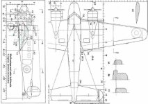
I´ve e-mailed the top and side view drawings to you. They will be better resolution than the atatched pic, and I hope they are good enough.
The aft part of the nacelle merges with the wing about half way along the chord. From the available drawings it is not very easy to see exactly, but I have drawn the lines that would correspond to the nacelle profile, marking the point at which the top and the bottom join with the wing profile, 2.25 ft aft of the point I marked as Centre of Gravity.
Cheers,
Aleatorylamp
 

Attachments

  • Plan.jpg
    Plan.jpg
    87.2 KB · Views: 0
right, thank you very much.
the email has been received.
the top down view is especially helpful.
i wasn't aware of the extra curvature
in the forward nacelle.
it's very art deco...cool.

i'll make the appropriate changes
to the nacelle template sizes.
of course this means the wing to nacelle
intersection points will change.
but, what the hell, live and learn.
and if you don't learn,
do it over until you do.

i'll also reshape the aft nacelle,
from the current chop off at -2.25,
to a nice tapered curve coming to a point
and merging with the wing panel at -2.25.

would you mind if i played
with the chord profile,
maybe, just a little a bit?
nothing too drastic,
just adding a few more vertices
to give it a little more curve and flow.

i figure, what the hell?
since i'll, basically, be starting over,
why not make it pretty?

sure wish i had a bottom up view,
but, we can't have everything.

have a great weekend


ps...apparently, i'm getting into this.
way to go, Stephan, thanks.
at least, i'm not watching so much tv.
 
WHAT A DUNCE, I AM!!!

i was so enamored by the beautiful curves
of the nacelle/wing top down view,
i spent several hours, last evening,
doing my best, readjusting templates
to duplicate those curves,
completely forgetting what i was looking at.

those curves are NOT the shape of the nacelle.
they are merely the outline of the wing
where it intersects with the nacelle
that is protruding through it.

good luck duplicating that, sport.

the nacelle profile templates
will have to be a much smoother rounds,
with, say, 26 vertices...the ad2k maximum.
the wing profile will also have to be
much smoother with many more vertices.
much more like the wing profile in the side view.

yikes...now, there's a project to consider.
it's 02:10 am.
i should go back to bed
and continue dreaming.
who knows, maybe i can dream up
a viable compromise.
 

Attachments

  • -2017-jul-15-001.jpg
    -2017-jul-15-001.jpg
    33.9 KB · Views: 0
Hello Smilo,
That blueprint looks very intriguing!

Of course you can increase the vertices to make the shape rounder.
That would also be great, thank you very much!

I have found no bottom-view drawing or photos showing details of the
nacelle shape and the tucked-in wheel, so I suppose we will have
no other alternative but to deduce from the side-view.

Have a nice weekend too. We are having another heat wave here...
Cheers,
Aleatorylamp
 
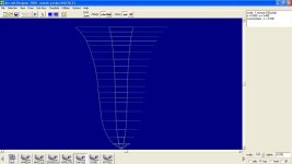
yeah, it's cool looking, but, unfortunately,
it's just pretty garbage. the only real value
might be for another side view layout.

with that in mind, i've continued
the upper and lower lines of the aft nacelle
on the side view drawing you sent.
from there, i'll use that full nacelle profile
to help build a new nacelle.
then, we shall see how the wing intersects.
i'll probably use 16 or 18 sided templates
for the nacelle...26 is overkill.

i've also delved into the wing profile templates.
as stated numerous times,
i am less than ecstatic with the three options.
the flat bottom to the trailing edge
on two of the options is ridiculously annoying.
which leaves the simple seven sider.
with all other template types,
you can edit their layout
after they have been constructed.
not so with wing profile templates.
line length and angles must be inserted
correctly during construction.
that's all well and good
if you know the line lengths and angles.
i don't...bitch, bitch, bitch...
quit your whining, smilo, and get to work.

side note;
have you noticed,
i love the word nacelle?

have a great weekend.
drink lots of fluids and stay cool
 
Bottom view!

Hello Smilo,
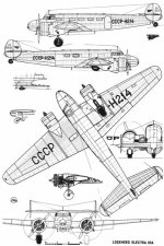
At last! I found a picture that includes a bottom view and I´ve e-mailed it to you. Here´s a screenshot too.
the shape there is quite predictable, but at least it confirms what one could deduce from the side view.

Using the 11-sided flat-bottom profile, perhaps once the wing and nacelle is completed, the trailing edge
of the flat bottom panel can be untied and brought forward, and the edge of the top panel there could be
lifted, and an extra panel inserted, which would correct the trailing edge of the wing.

Then, the forward vertical leading edge panel could be untied, brought backwards, and
split into two to give the leading edge a sharp front.
Cheers,
Aleatorylamp
 

Attachments

  • bottom view.jpg
    bottom view.jpg
    67.4 KB · Views: 0
email received...in a word, FANTASTIC!
incredible detail and clarity...thank you.

and with interesting soviet markings.

will most likely spend the weekend
playing with wing profile template configurations
and will then, seriously consider your idea.
i'm also considering the use of two separate,
but, overlapping wing profile template classes.
it might be too complex..we shall see.

i sure wish i knew how to hack this program
and simply improve the template options.
while i was in there, i'd also move the delete button
or at least, make it ask if i want to delete a chain.
i've accidentally hit that damned thing,
one too many times.
bottom line, i don't know how to hack the program,
so, i'll have to be careful,
make do with what i've got
and save, save, save.
i'm actually thinking of setting a timer
to go off every ten minutes,
just to remind me to hit the save button.
 
Hello Smilo,
What is interesting in the bottom view I suppose is that the wheel well includes a narrower forward open section to cater for the landing gear strut. On other planes the strut had a plate that would cover that section, so only half the wheel would remain visible outside the well, and this plate would also act as an air-brake when the gear was extended. On the Electra it seems that it was simplified - although the gear did have mudguards!

Regarding the wing profile and nacelle parts intersection, we´ll see how the results of the different possibilities develop, and then take a decision on the best solution to be used.
Cheers,
Aleatorylamp
 
progress (?) report;

have i ever mentioned, i'm scattered?
can't stay focused on a task?
probably, borderline Attention Deficit Disorder.
whatever...i deal with it.

the point being, i decided to rework the wing.
can't have a good intersection without it, right?
spent quite a while getting the biconvex (7 side) template
to fit inside your hand drawn profile.
but, finally got it done...close enough.

INTERUPTION!...

i received the latest set of pictures and noticed
the nacelle shot with wings removed,
which in turn got me to thinking
about cleaning up that exposed chord.

OH, WAIT...
didn't the other plans
have bulkheads and a chord?
yup...sure did.
so, making a long story longer,
i cropped out that chord,
cleaned it up and now have
a pretty good working example.
that done, i set up an ad2k rough draft
with the seven main vertices
and have now connected the dots.
what i have, is what looks like a biconvex(7) template.

if i had a printer, i'd make a hard copy
and use a protractor to measure the angles
so i could easily transpose them
to the ad2k profile template creator.
but, no...i get to hunt and peck
until i figure them out.

hmmm, maybe it would be easier
and save time, if i'd just copy the drawing
to a flash drive and go get it copied in town.

by the way, do you have the length
of the chord if it was placed mid fuselage?
 
Back
Top