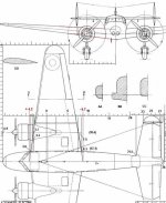
Lockheed Electra Model 10

Hello Smilo,
I see you are working very hard indeed, trying out different
possibilities!

The equivalent of the chord of the wing profile at the fuselage
centerline would be 12.9 ft. The position of the leading edge
would be at +4.2 ft, and the trailing edge at -8.7 ft. of CoG.

Then, profile thickness at the nacelle centerline is 2 ft, but along
the fuselage centreline, it would be 2.5 ft.

Hope this helps! Cheers,
Aleatorylamp
 
yes, it does, very much in deed, thank you.

while i have your attention,
at the risk of being critical,
(which i am not)
where did you come by your chord profile?
was is from the side plan.jpg,
highlighted in green?
the reason i ask is that yours seems to be wider
in proportion than the example DD
in the upper left corner of Top-plan.JPG
granted, the DD example is mid wing,
but, the thickness discrepancy is substantial.

update;
i just ran the numbers for length to thickness ratio.
the root wing profile, 12.155 long by 2.706 wide.
dividing length by width, i get 4.492
at fuselage center, 12.9/2.5= 5.16
now the kicker. using the DD example,
i could only count pixels and got 156/27= 5.778

so, my question...which ratio do you want to use?
or, do i have it all wrong?
 
Hello Smilo,
Yes, I see what you mean.
I had taken the measurements from the front and top view drawings. There seems to be a discrepancy with the dimensions on the side-view drawing which I hadn´t noticed before. I wasn´t using those because the red and light-green lines there were drawn in by hand by myself, and could perhaps be a bit off! I´m terribly sorry.
In red, I´ve drawn in the sizes for the chord length and thickness on the top and front view drawing. Would you be OK with that? I´ll e-mail it to you too, because of the resolutioin.
Cheers,
Alñeatorylamp
 

Attachments

  • Top-plan-.jpg
    Top-plan-.jpg
    56.1 KB · Views: 0
no need to be terribly sorry.
things happen...don't worry about it.
please email the modified drawings.

have been up for a few hours tonight.
am setting up a grid to layout
the chord profile at 12.9 x 2.5.
will then use it to build a biconvex template
to fit inside a new hand drawn chord profile.

....starting to crap out, so, it's back to bed.

i won't get much done tomorrow,
will make the hour trip to the ferry terminal
to pick up a family member flying into seattle.
 
Hello Smilo,
I just noticed I had sent the e-mail with the top-view and front-view drawings as a reply to the SOH Forum notification...
where it will be ignored! So, I´ve just sent it to you!
It was easier to use those views because of the continuation in straight lines toward the fuselage centreline.
Cheers,
Aleatorylamp
 
to say the least,
the past couple weeks have been a struggle.
with the frustration of trying to figuring out
the the ad2k wing profile template procedures
being compounded by the big monitor
slowly giving up the ghost,
i finally had to step back for a bit.

yesterday, i took a bite of the bullet,
broke down and bought a new 48 inch tv/monitor.
...what a difference a few hundred dollars makes.
now, i can actually, see what i'm doing.
what a concept.
the next step is to motivate the self
to attack the profile template issue again....:a1089:
 
Hello Smilo,
We are having such a hot summer here that it´s hard to do anything on the computer.
I was trying out a few work-arounds for this wing template thing, but none worked.
Let´s see what I can do as soon as it gets a bit cooler.
Cheers,
Aleatorylamp
 
Hello Smilo,
There´s greater difficulty than expected for twins in AD2k as regards nacelle/wing vertex adjustment, which didn´t apply to single-engined plane modelling.
Let´s see if and how it can be worked out.
The bog-down is such that the more limited yet more familiar AF99 is again bekonning from a distance, and I´m once more tempted to switch over.

Cheers,
Aleatorylamp.
 
it's clear that detailed chord profiles
were not a high priority
when ad2k was designed.
so it goes.

i don't know how long i've been trying
to just build a simple 8 sided profile template
with the vertices where i want them.
i type in the angles and coefficients,
OK out of the template editor input panel,
then, go back into it to double check.
oh goody...
the program has readjusted them for me.
...followed by a long line of profanity
trailing off into the darkness.
i neither want or need the numbers
adjusted for me...thank you very much.
leave them the hell alone.

after a while, i gave up
and built a simple 6 sider
and a 7 side, biconvex profile template
that align (close enough) with key vertices
on the hand drawn chord.

after a break, i'll continue
to dink around with the 8 sider.

i sure most of the ad2k problems
are self inflicted, ie, operator error.
i'm just stubborn enough
to take it as a challenge
and will continue to fight on.
 
Hello Smilo,
I went through that ordeal too! Changes in any of the profile templates NEVER come out as you need! Frustrating indeed...

I´m sure it´s a programming bug, and not the user not doing something correctly! Plus, the fact that there are only 3 profile templates to chose from, makes the whole thing questionable too. They did notice... but didn´t publish a bug-fix. They only improved the profile templates for AD2K2 - incompatible for our needs though!

So, with this rather big let-down, I am coming to the conclusion that AD2K is fine for single engined planes, or maybe twin engined jets, with their engines attached to the rear fuselage.

I doubt that it will be worth while to continue torturing ourselves with this issue!


Cheers,
Aleatorylamp
 
au contraire mon frère,
you give up too easily.
i, on the other hand,
am a glutton for punishment.
where there is a will,
there is a way.
i will not be thwarted
and will continue to muddle on.

this is "fun"(?)

actually, the fun part
is coming up with a solution.
 
Hello Smilo,
OK, ok...
If it´s not one way, then it´s another.
If the worst comes to the worst, we´ll fit the nacelle panels manually!
Cheers,
Aleatorylamp
 
that it is, my friend, that it is.
i'm reminded of a story
about an old lady's epitaph,

SHE DIED OF ODTAA

one damned thing after another


how about this?
why don't we attack
this issue from two fronts?
when you have time,
build a wing, from fuselage center
to pre-cap tip using af99.
make the chord as complex as you want.
if possible, add chord "bulkheads"
at flap and aileron locations.
bulkheads, both inside and outside
of the nacelle would be a bonus.
when done, send me the afx files
to import into ad2k.
remember, no structures or components.

i'll continue trying to solve
the profile template fiasco.
the nice thing about templates,
is that they can be covered,
moved and resized to reflect
the angle and taper of the wing.
that's, basically, why i'm bothering with them.

thinking about this,
it's not a multi-engine issue.
to my mind, it's more
of a poor wing template options issue.
i, obviously, am asking for much more
than the program has to offer.
i may be kidding myself, but,
i feel that, if i can come up with
a satisfactory basic profile template,
i will be happy.
actually, there's more to it than that,
but, you get the idea...right?
 
Hello Smilo,
Thanks!
OK then: I´ll make an AF99 wing with an 11 or 12-sided profile, starting from the fuselage centreline.
I´ll insert bulkheads at fuselage centre-line and wall, at nacelle-centre and inner and outer walls, and at wing-tip base - also at inner aileron end (outer end coincides with wing-tip base),
Flaps were of the kind that came down under the wing, and seen from the top there´s no cut-out.

I understand that the 11 or 12 wing-panels are to be in one piece each, going from the fuselage centre to the wing-tip base.
Nose to the grindstone!
Cheers,
Aleatorylamp
 
eleven or twelve panel wing would be great.
...while i'm in wish mode,
how about six chord bulkheads?
one fuselage center
one about a foot out from the fuselage wall
one about a foot in from the inner nacelle wall
one nacelle center
one about a foot out from the nacelle wall
and finally, one at the wing tip

i sure hope that isn't too much to ask for
 
thank you, i look forward to it.
as always, no rush.

made some progress with the simple 8 last night.
nothing to get excited about, just baby steps.
but, i believe it was progress.
 
Hello Smilo,
OK, so attached herewith are the AF99 wing parts for Lockheed L-10 Electra:
6 Wing-profile bulkheads:

-Central fuselage line bulkhead
-1 ft out from fuselage wall
-1 ft inside from nacelle
-Central Nacelle
-1 ft out from nacelle
-Wing tip base

15 Wing panels:
-8 top panels, "w-panel1" to "w-panel7"
-7 Wing under panels, "w-panel-u1" to "w-panel-u7"

The wing-profile has 13 vertices. Have a look to see if everything´s ok!

Cheers,
Aleatorylamp
 
that was quick.
thank you, Stephan.
downloaded and will transfer
to the design machine now.
will report back, asap
 
Back
Top