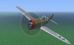
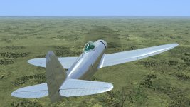
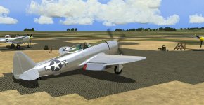
P-47 Progress Thread

Just for fun, a 30s. video of the flaps being deployed in gmax. In the real aircraft, the maganta parts are linked to a torque tube that runs the span of the flap - see posts #59 & #72 of this thread. There are slots in the trailing edge of the wing for the green arms. These are already cut but I can't decide whether the slots were covered by spring-loaded covers (such as the one nearest to the fuselage) or left open. Museum and flying examples seem to have them seldom installed. The flap deployment starts about 3-4s. in and is repeated once:

Wow Joost, that's a very cool bit of animation, talk about a labour of love! :applause::applause::applause:
 
... talk about a labour of love!

Haha, more like out of necessity!
I knew about the page Andy linked to (thanks Andy!), so I had a rough idea how the thing worked but to create a more accurate rendition, I had to model most (and specifically the visible) parts of the system. Drawing circles with all parts' axes as a center to show their range of motion, I animated the whole contraption using the points where the circles intersected. The result is the animation shown in the post above. I think it is quite accurate: at first, the flaps slide mostly back and a little down (also to clear the wing fillet. Straight aft is not possible, as part of the flap is tucked under the fillet) and only near the end they start to rotate downwards.

Currently, the ingame flaps animation has 4 settings: 10, 20, 30 and 40 degrees. This was not the case in the real aircraft: There are only three positions for the flap lever - 'Up', 'Neutral' and 'Down' and no flap gauge or anything of that sort. To get to a certain flap setting, the pilot moved the lever to the down position and when the flap reached the desired angle, he moved the lever to 'Neutral'. Leaving it in 'Down' gave full flaps. Retracting the flaps was a similar, but opposite, affair using the 'Up' and 'Neutral' positions. To aid the pilot, there was a stencil on the outboard side of the flap showing the approximate flap angle, see the first piccie in post #72 of this thread. When viewed from the cockpit the first two of the four flap settings do look like the flap is sliding more aft than rotating downards. Again, a short video of just the mechanical linkage created. Only the torque tube has been omitted for the final model because it isn't visible from the outside:

https://vimeo.com/502942744

I also found a short YouTube video of an RC P-47 model with a similarly modeled flap drive system. Though I usually regard plastic and RC models with a suspicious eye (as they're not always true to the real deal), this one seems pretty accurate and shows the same animation:

https://www.youtube.com/watch?v=bqJ5n_55utU
 
Really excited to see a well done P-47. Thought it always needed attention in CFS3. Thanks for doing this Frosty ! Hope things are coming along nicely . Regards,Scott
 
I have run into a few texturing snags which I hope some gmax guru can help solve:

1. I have model parts that are partially aluminium, partially plexiglass (the canopy and the fuselage/windshield). When applying a material it therefore seemed logical to create a multimaterial with the properties of aluminium and plexiglass. The parts are mapped to the same texture sheet. Somehow I can't seem to get the plexiglass very shiny or reflective: When I add a diffuse map to the plexiglass material and set the opacity, I can get it very shiny but I lose the opacity. If I don't apply a diffuse map and set the opacity, the glass stays rather dull. I am a bit puzzled here!

2. When applying the multimaterial to certain model parts, they do show the texture but not the material properties (metalness, shine etc.). I have removed the material from the parts, applied it again but this doesn't solve the problem. If I create a new, separate standard material, they pick it up fine... Any idea why this is?

Thanks!
 
With the aid of Dan I managed to tackle the secret to shiny plexiglass:

Teaser33.jpg

I am pretty pleased with how it turned out. To my eye the plexiglass canopy really does look like..er.. plexiglass!

Unfortunately, the model shown above will not be continued: when riveting the underside of the AC I noticed some discrepancies which prompted me to review the blueprints. As it turned out, there are two frames 101 5/8, a forward and a rear one, 8 inches apart, something which I somehow managed to miss or ignore before. So the model is 8 inches short! I had to cut the model apart, surgically insert this bit, re-attach the wings etc. and had to partially remap the external model. Because I had made some alterations to the mapping itself and had to move the parts around a bit on the texture sheet to fit this extra length in, I could also discard most of the previous riveting. Back a few squares!

I also took the opportunity to make a few extra cuts to assign those parts different material values in the hope that it would give a better final result. The good news is that progress isn't bad and that I have already riveted some parts I hadn't done before:

Teaser34.jpg
 
I wonder if this is where that extra 8 inches came from:

"P-47C-1-RE, with 8-inch fuselage extension to move the center of gravity, improving flight characteristics. Minor changes to the main undercarriage were made, and tailwheel steering was omitted. Other minor changes were made to the turbo-supercharger air duct, elevator control system, and controls. 54 built, plus one P-47C-RE modified as the prototype."

https://en.wikipedia.org/wiki/Republic_P-47_Thunderbolt_variants#P-47C
 
Wonderful to see progress being made on you beautiful P-47 ! Keep up the good work. Love the P-47 and it's time it was given justice . Thanks so much for your time and effort ! Regards,Scott
 
With the aid of Dan I managed to tackle the secret to shiny plexiglass:

View attachment 83522

I am pretty pleased with how it turned out. To my eye the plexiglass canopy really does look like..er.. plexiglass!

Unfortunately, the model shown above will not be continued: when riveting the underside of the AC I noticed some discrepancies which prompted me to review the blueprints. As it turned out, there are two frames 101 5/8, a forward and a rear one, 8 inches apart, something which I somehow managed to miss or ignore before. So the model is 8 inches short! I had to cut the model apart, surgically insert this bit, re-attach the wings etc. and had to partially remap the external model. Because I had made some alterations to the mapping itself and had to move the parts around a bit on the texture sheet to fit this extra length in, I could also discard most of the previous riveting. Back a few squares!

I also took the opportunity to make a few extra cuts to assign those parts different material values in the hope that it would give a better final result. The good news is that progress isn't bad and that I have already riveted some parts I hadn't done before:

View attachment 83524

Ah a rivet counter, I like it!:biggrin-new:
 
Really exciting to see such a quality model of one of my all time favorites for WW II. Please keep us updated. Thanks for your passion and hard work ! CFS3 is alive and well ! Regards, Scott
 
Frosty, just was wondering how things are coming along ? Really excited to see such a nice P-47. One of my all time favorites getting all this attention is nice. Thanks for all the time and effort ! Regards,Scott
 
Thanks for your interest in my humble work ;-)
Currently I am still riveting the external model, which is the most tedious job you can imagine: It's studying blueprints, reference photos, counting rivets, and painting them on the texture. As RL is a priority on weekdays, it leaves mostly weekends for texture painting. This makes progress slower than I like but I have already placed more rivets on this newer, longer model than on the old one. So that's good. You'll get a screenie when I feel there's enough to show ;-)
 
Thank you for all the passion to get it right to begin with. Makes it all the worthwhile to wait. I'll be around a long time,Lord willing, so i have patience . That's one thing this sim has taught me... Regards,Scott
 
Well Scott, here's your update:

Rosie's got a sore right arm from placing so much rivets but since she's nearly done with the outer skin panels, I gave her a day off. I used a spray gun to apply some basic colours and took out a polishing rag to give the aluminium a good rubbin'. Then I tried to clean up the PS template to reduce the size and make it easier to use. After that, I gave the engine a test run and admired my work of the last week:
 

Attachments

  • Teaser35.jpg
    Teaser35.jpg
    573 KB · Views: 217
Uh, Joost - I hate to say it, but three rows back from the windscreen aft frame, two sections down, it looks like one of the rivets isn't properly set. You'll need to go back and drill that one out and try again. :a1310:
 
Uh, Joost - I hate to say it, but three rows back from the windscreen aft frame, two sections down, it looks like one of the rivets isn't properly set. You'll need to go back and drill that one out and try again. :a1310:

Lol - you just wait until my eight tons of vertices fall upon your puny Mk.V!! :biggrin-new::playful:
 
Looks superb mate nice work, for the complete noob (yep me) do you have to do all the rivets for each skin or do you just skin over the top and the rivets show through?

Mick
 
Back
Top