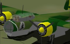
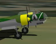
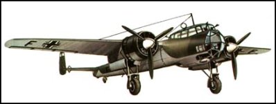
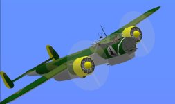
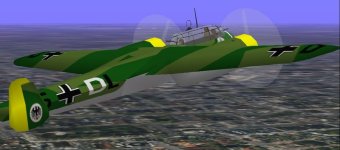
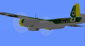
Project Dornier Do-17z2

Hello Smilo,
OK, thanks, but not to worry! At least you have the latest version again - no harm done!

I now have an idea for the canopy glue sequence - at the moment the forward crew members seem to be more or less OK under the canopy. I studied Ivan´s sequence for the AT-9 Jeep and it´s a little different: It has 2 pilots and 2 seat-backs, but I think I can deduce the principle. It seems to follow a path, so that at the end all the parts involved end up under the canopy, so I´m trying to get there now! At the moment the rear cabin floor, gunner and gun are glue-sequenced, but do not end up under the canopy...

I´ll also inspect some vertices to see if I can get rid of some more strings of pearls.
I appreciate your efforts helping me out! It just proves that four eyes see more than two!
Cheers,
Aleatorylamp
 
i'm pleased to be able to help.
as is well known, this is an aircraft
i've wanted to see for many years.
i'd all but given up hope of ever seeing it.
as a matter of fact, i had given up.

i'm flying it right now on another machine
and noticed something rather funny.
in spot view, zoomed in on the canopy and crew,
from the forward left view,
i pressed the key for head on view.
as the view slowly panned,
the pilot and bombardier facial expressions
change as it approaches and passes center.
i don't know if it's intentional or not,
but, it's hilarious....please, don't change it.
 
Running into problems!

Hello Smilo,
The facial expression thing is not intentional - except for the bombardier´s head turning with the rudder control...
I´m trying to fix the rear gunner, gun and rear cabinfloor interaction with the rear cabinglass. And the thing is the cabin reaches beyond the cabin component, invading the mid fuselage section. Difficult balancing act, and now I´ve discovered a wingroot bleed with the lower belly, and I´m working on it.
We´ll see...

Update:
In the latest version, No. 4, if you look from above-side down on the wing-root, the bottom of the fuselage bleeds through. This is because the wing roots are now grouped in Body Main. Trying to get rid of this I ran into all sorts of complications,which included bleedthrough complications with the canopy seen from directly below and also resulted in the Animation programme hanging up, so I´m backtracking and have sorted AA out.

So basically, wingroots have to stay in Innerwing mid left/right that caused the
momentary minor bleed of the inner wing-root through the engine nacelle - now the lesser of the evils. Hence, I suggest reverting back to a previous version, but with corrected exhausts etc., and from the opinion in your two recent posts, I can clearly see that you would agree!

So here is Version 5, (inc. AFX) with the smaller recent corrections on the exhaust, etc. For the moment, I think this is the best one, but as I said before, I´m still trying to sort out the rear cabin.

Sorry about the confusion, but sometimes this happens!

Cheers,
Aleatorylamp
 
Last edited:
Hello Aleatorylamp, Smilo,

Happy New Year!
On Chinese New Year, we had guests over and yesterday was BUSY!
I didn't have a chance to check in here until late a night and with the iPad, I wasn't about to type a long message.

I am glad things are going well on the model.
I haven't had a chance to download or look at anything yet, but perhaps I can still throw a few ideas out there.

Smilo,
I am glad you are finally getting the aeroplane you wanted.
Pity mine hasn't come to anything, but with all the research I have put in recently, I am likely to at least add a few details.
I certainly know more now about how the aeroplane looks than I did a few years ago.
The trick now is to get a Development machine running and the time to do some designing.

Aleatorylamp,
If you still have a significant number of Parts remaining, you might want to consider adding in Cheek and Chin Windows and perhaps a few other distinctive little bits for your aeroplane.
To each of us there is a set of recognition features for an aeroplane and I was pretty sure I could not get them all in to my satisfaction within AF99 limits

In my opinion, you were more correct with your earlier Exhausts that extended well above the Cowl.
Those pipes really did stand quite high on the versions that had them.
Check some photographs and you will see what I mean.
Other versions had what I believe were individual exhausts at the rear of the cowl.
What I haven't figured out is why those exhausts on top didn't tend to leave a lot of staining as one would expect.

Regarding the mismatch between a Structure and Component, there IS a solution that I believe will work:
Bring up the junction in AF99 magnified as high as you can to see where the mismatch is.
Create a new Bulkhead Part that matches the Component or Structure, whichever is bigger.
You probably won't be able to match the Structure's vertices exactly which is why there is a problem.
What you do is where it is slightly smaller, use the Point Editor to make it extend slightly past the edge.
The 0.01 Foot size difference won't be visible except inside AF99 but by adding this new Bulkhead Part, you will hide the mismatch with a cost of only two additional Parts to your project.

If you don't want to add a Bulkhead, you can also add it to the Component but then you might have to resize the end of the Component so that it matches the new Bulkhead.

Today, instead of Guests, I have a very sick Child to watch out for..... It will still be busy.
- Ivan.
 
Hello Ivan, Hello Smilo,
Yes! Happy New Year 4079! May it bring happiness to you and your families, and Ivan, a new life into your development machine - good to hear you had a nice time with your folks. Parties are important!

Thanks for the precise indications on joints between component and structures. I´ll have a try with the fuselage - the main places are near the trailing edge and near the tail.

As regards chin and cheek windows, I know you have mentioned them before, but I´m a bit at a loss here.
I thought I´d got the chin windows in already. I just had a look at the photos and noticed that the cheek window is only on the starboard side. OK, I´ll try to put that one in!


With respect to the exhausts, re-instating those structures would involve taking out the Bombardier again. Parts count is at 147.9 now. I didn´t think the exhaust structures came through very well though, and I´d say the Bombardier adds more ambience. But then, it´s sixpence of one or a half a shilling of the other... I wonder...

Smilo, with my recent "improve-worsening" that I had to backtrack, I forgot to put back the insignia-up for the rear cockpit-floor in Version 5, but I´ll fix that for a further improved post in the next couple of days. Anyway, I´m certainly very glad to see that you are enjoying the model, and that it´s slowly reaching the finish line. Very pleasing.

Cheers,
Aleatorylamp
 
Hello Aleatorylamp,

Thanks. I didn't say I enjoyed the event. I just said there was an event that we hosted... ;-)

The development machine(s) will probably be down for a while but perhaps I can get something installed on my laptop which seems to be the easiest computer to deal with at the moment.
I think I even have a USB Joystick around somewhere.
Typical of the multiple directions is the idea that with all the research and looking at photographs, I should at least do a few additions on my version of the Dornier.
I still haven't finished the panel for the BV 141.
I have been researching the Airacobra as mentioned elsewhere.
I am playing with drawings of the Corsair..
I am also doing some programming for the Propeller Tables. (Remember the Hex Editor?)
Due to other unresolved issues, I don't spend all that much time on all of those combined.....

Regarding Windows on the Dornier 17Z / 215:
There are actually TWO Starboard Windows and one small Port Window and a small Chin Window on the underside.
Photographs of the Dornier 17 being restored at the RAF Museum clearly show where the heavy structure ends at the nose and how much is actually just light framing and glazing.
If you are running out of Parts, you can get most of the same effect with putting the Windows into the textures for the aeroplane.

Got a sick Daughter that needs attention....

- Ivan.
 
Hello Ivan,
I see... It´s better to be too busy than bored, at any rate!
I´ll have a closer look at the windows on the RAF museum machine and see what I can do.
Thanks for your indications, and hopefully the laptop installation will be fruitfull.

I´m now figuring out the rest of the glue-sequence for the rear gunner and cabinfloor. Let´s see if I can get it as nice as the one you had for the AT-9 Jeep with the 2 crew members, and behind, their seatbacks and the rear cabin wall. This time at the back it will be the gunner´s head, the gun and the slanted cabin floor. It´s rather similar, so it should work...

Update:
Ha! I got it! It works! I have managed to apply your "conga": The glue sequence dancing first between heads and torsos of the bombardier to the pilot, then to the rear gunner´s head, the gun and the rear slanted floor, then back to the main cabin floor and then to the canopy frame and windows, and it works! Ha! The rear gunner´s had and gun no longer bleed through the fuselage seen from below, and the windows glass is fine now!

Cheers,
Aleatorylamp.
 

Attachments

  • cabincrew.jpg
    cabincrew.jpg
    44.6 KB · Views: 0
hello Stephan,
sorry i didn't find these sooner.
they, most likely, would have saved
you time and aggravation.
notice the hatch with window,
left side aft, near the trailing edge.

personally, i don't think this detail
is going to matter that much,
but, i'll leave the choice to you.
at least now, you have the information.

ps, i've included a cockpit drawing
in case you don't have one.
 

Attachments

  • do17_Cpt.tif
    13.1 KB · Views: 0
  • do17_Rt.tif
    13.1 KB · Views: 0
  • do17_Lt.tif
    12.9 KB · Views: 0
  • do17_Btm.tif
    18.2 KB · Views: 0
Chin and cheek windows, right side

Hello Smilo, hello Ivan,

Thanks for the diagrams, Smilo! The small window at the back will be easy. No problem to fit into the fuselage texture. As it´s far away from the other glazed sections, I think it will not look odd.

I put in the check and chin windows on the right first as grey or dark grey insignia rectancles, but that did look odd. Now I have them textured into the fuselage-front. It looks better, but I´m not sure if I like them very much as they aren´t transparent and so, don´t match the rest of the glass. Does this look OK?

Making them transparent will be complicated because the inside has to be blocked off differently from the left side, and the grey walls needed to do this will probably cause extra bleeds, but I could try...

Update:
Fuyther to the rear-cabin interaction - it is not totally perfect yet, and probably won´t be 100%. The outside of the gun disappeared against the housing around the canopy as it was outside the whole thing, so I separated the barrel from the butt and also separated it from the body with glue, but now momentarily the lower fuselage floor around the ventral window and the gun bleed through the top a little... It never stops, does it?!
Oh, well...

Cheers,
Aleatorylamp
 

Attachments

  • chin+cheek windows.jpg
    chin+cheek windows.jpg
    39.9 KB · Views: 0
Last edited:
Hello Smilo,

The Starboard side Cheek Windows are incomplete on the drawing that is attached but I think Aleatorylamp figured it out from the Photographs which are already in this thread because he also has the upper Window on that side.

Hello Aleatorylamp,

Have you thought about doing the windows as a Transparent Texture / Alpha Channel?
In that manner, it doesn't cost you any more Parts and you can make them as dark or transparent as you like.
There is another neat little trick with adding a couple extra Internal Parts to the Nose Component which will only be seen where the pieces are Transparent, but it is hard to test things out without a working Dev machine.

- Ivan.
 
maybe this will help...

hey, while we're at it,
how about that circular antenna?
sorry, i can't remember the frequency.
 

Attachments

  • 2WWdo17z.jpg
    2WWdo17z.jpg
    14.2 KB · Views: 0
Hello Smilo, Hello Ivan,
Smilo, you do have a point with the circular antenna!

Ivan, I´m not sure if I understand.
Probably it´s not what you mean, but as far as I can understand, AF99 does not support transparent texture sections on a part - the whole part has to be transparent, but that means that what´s behind it disappears... so a transparent part on the cabin side can´t be a part of the component but has to be an independant one, and won´t let you see the inside of the cabin... But.. you must be referring to something different, I´m sure.

Cheers,
Aleatorylamp
 
no, i don't have a point.
other than i was being a nitpicking ahole.
maybe, i should delete the comment.
what do you think?

my apologies...it's no excuse,
but, i'm a little under the weather.
and no, i'm not looking for sympathy.
 
Hello Aleatorylamp,

Actually, I don't know if my idea would work anyway, but here was the thought:
If you are too close to the limit for Parts, you can change your texture to use Black as a Transparent Colour.
Then, if you select the proper Speed Below code in AF99, Aircraft Animator will treat it as an "Alpha Channel" piece and make the Black areas of the texture Transparent.
Hubbabubba used it on the rear Wheel Well of his Jeep and I use it on my SBD Dauntless Dive Brakes because without it, I could never put in all those holes that are necessary.
The problem I believe (and this is why it may not work) is that you only have a choice of a regular texture on the piece or a Transparent area. There is no in-between.


Hello Smilo,

Not all of the Dornier 17Z-2s had that DF Antenna or the fairing under it.
I don't think Aleatorylamp has the extra resources needed to make that happen anyway.
That is why I am only suggesting features that are present in ALL of the Z-2 subtypes.
Note also that the Nose Gun normally had a frame supporting it, but not all of them did which is why I haven't mentioned it.
Same goes for the "Fenders" on the undercarriage. I am sure that someone out there operated without them.

Most of the construction in the basement just finished up a few minutes ago. All that remains is the floor.

- Ivan.
 
Hello Smilo,
I put the radiogoniometer on the Baltimore so why not on this one... I think this model had one.
I even saw one with the base but no circular antenna on it. Maybe it was removable. I think it´s a good idea which I missed.


Hello Ivan,
OK, thanks, I´ll see if I can apply the new idea for the extra windows. Trying sth new is appealing in itself!
Yes, and I´ll have to forget about the fenders - of course!

Well..., once the extra window thing is satisfactorily decided, I´ll finish the textures and do the SCASM VCockpit and the plane will be finished! So, the light at the end of the tunnel is visible!

BTW, I think I`ve solved the bleeds with the lower gun station and the upper fuselage! A relief.

So, especially for Smilo, here´s the model again, Version 6 now, with the recent small improvements, especially with Ivans "conga" for the cabin inhabitants, and also with the radiogoniometer! Ho Ho! I made them with two very close concentric circles, as one is is not very visible. ...but the extra windows are still in the making.
Parts count has crept up to 148.4% - and we have all of 13 parts left over...

But... there are still a few bleeds seen from underneath. Darn!

Hopefully you will get out of underneath the weather, Smilo!


Cheers,
Aleatorylamp
 

Attachments

  • model pic.jpg
    model pic.jpg
    30.1 KB · Views: 0
Last edited:
Looks pretty.

On a technical note, where is your division between the Nose and Fuselage?
I am wondering about the replaceable Nose for Night Fighter and other variants.
You realise that with the proper replacement pieces, you can have earlier Dornier 17s as well?

I have been re thinking the division on my own model:
As you can tell from the screenshots, originally it was intended to be a sloping joint with the upper part further aft than the lower part.
I am now thinking that the upper Canopy end can line up with the forward edge of the Bomb Bay and it can be a vertical separation.

- Ivan.
 
Hello Ivan,
Thanks! At least it looks pretty!
Nose/Fuselage Division? Good question, and maybe it´s not the right place. I hadn´t thought of it...

Come to think of it, that could be one of the major problems. Only the front glazed part is in the nose group.
On the screenshot the nose part is in light blue. Also, the equivalent of a dashboard is there, but with no instruments and with insignia rear, to block out most of the Nose group from the interior view.

Updated line: From what you say, and from your screenshots, I now understand what you mean: The Nose/Fuselage division could slant from the rear of the upper canopy down to about just infront of the lower gunner station, or go almost vertically down from the same starting point to just aft of the gunner station.

Yes, there could probably be a total of three extra variants of this base model. The Kauz night fighter with a solid nose would be easy to derive. That one was also a bit more exciting with 265 mph. Then, maybe with a different shape, also the much faster Do 215. The earlier ones (900 Hp at S.L.) would also fine, and could include a bit of an assymetry on the left front of the canopy.

Cheers,
Aleatorylamp
 

Attachments

  • nose division.jpg
    nose division.jpg
    23.6 KB · Views: 0
Last edited:
Problematic trial transfer of parts

Hello Ivan,
I did an initial trial transfer of everything under and forward of the canopy upto the ventral gunner position into Nose, and there is interaction between the rear cabin and the forward engine nacelles+props+spinners which are in Nose left/right. The rear cabin contained in the Nose portion seems to have priority over Nose left/right groups.

Another try, having forward engine nacelles in Inner-wing mid left/right instead of Nose left/right, won´t help either, as the large Nose group seems to have exaggerated priority over forward portruding wing groups, maybe because the cabin is so high?

Possibly the best division line would be in the centre of the cabin? That would require re-grouping of parts between the different forward fuselage components. I wonder. There is also the problem of splitting the canopy glazing and the canopy frame in two, and I have no more components left.

Then, a minor issue: Before, the bulkhead behind the front glazing, covering the nose interior behind the front glazing, was conveniently an insignia forward piece in Body Main as the fuselage ended there, but now needs to be glued inside Nose.

Experiments, experiments... we shall see!

Update: Well, not everything is successful... but we always learn, don´t we? That´s part of the fun.
The last build before the trial transfer was the most successful, with only the dorsal gun barrel bleeding through the fuselage seen from below - it was poking out of the "Cabin´s Conga".
Thus, reverting back to that build, I moved the dorsal gun barrel into Canopy High Wing together with the radiogoniometer and the antenna parts, and ... everything looks perfect! ...or so it seems, so for the moment I´ll stick to that.


Cheers,
Aleatorylamp
 
Last edited:
Tail emblem

Hello folks,
After the fortunate elimination of the upper gun barrel bleed, I´m now doing the markings on the textures (not the paneling as yet - that´s difficult...).

For reasons of historical accuracy, there should be a schwastika on the fins, but personally, I´d much prefer not to see one. Instead, I find the use of the German Eagle or an Iron Cross (like a Maltese Cross), more appropriate, as these have always been German military symbols. Here are 2 screenshots of the fins with a German Eagle on them.

Any opinions on this?

Cheers,
Aleatorylamp
 

Attachments

  • Tail emplem1.jpg
    Tail emplem1.jpg
    50.3 KB · Views: 0
  • Tail emblem2.jpg
    Tail emblem2.jpg
    21 KB · Views: 0
Hello Aleatorylamp,

Eeeeek!
I was not suggesting that you Re Group your project to put more pieces into the Nose Group.
I was just asking where the logical division between Fuselage and Nose were with the idea that the Nose would be switched between different versions.
It is a similar idea to my P-40 Warhawks; The whole aeroplane back to just forward of the Horizontal Stabiliser is common between Long and Short Tail. The pieces behind vary between versions. I didn't intend it as a discussion of what Group each piece should be in.
I was pretty certain from your "Updated Line" addition that you understood what I was asking.....
Sorry about sending a Rabid Goose in your direction.

Did you try the additional Bulkhead and did it work?

Regarding Swastika:
I understand that in Europe there are legal concerns with displaying a Swastika.
Personally, my own preference is to use them in the places they were originally used.
That does not mean I have any sympathies for Nazi Germany or for Imperial Japan for that matter.
In fact, the country that displayed the Swastika most prominently was not Germany as you probably already know: It was Finland.
The symbol is much much older than the nation we take it to represent today.
The symbol is quite common with Buddhist and American Indian decorations.
A Buddhist prayer recorder with moulded Swastikas as decoration was placed with the body of my mother in-law.
I even took a photograph of that box before it was left with her, but have no idea where the photograph is now.

- Ivan.
 
Back
Top