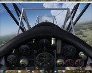
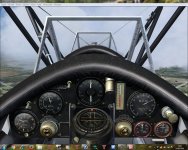
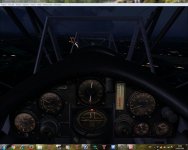
As the nature of things progress...

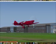
Sahara circumnavigation in the 621 finished!

Onwards north from the Straits of Gibraltar crossing as I airport hop my way back to Lossiemouth Scotland.

Great trip to help test out this little bird.. with a 'small' deviation from the Sahara trip to test the Lynx floatplane somewhere in the amazon! LOL

oh.. and somewhere along the lne.. my RAF silver gave way to my blue and white scheme.:encouragement:

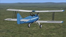
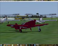
So.. here I am

Flying a plane over a plain in Spain.. .. and no rain!

So much for that saying!
attachment.php
 

Attachments

  • Untitled.jpg
    Untitled.jpg
    62.8 KB · Views: 6
Onwards north from the Straits of Gibraltar crossing as I airport hop my way back to Lossiemouth Scotland.

Great trip to help test out this little bird.. with a 'small' deviation from the Sahara trip to test the Lynx floatplane somewhere in the amazon! LOL

oh.. and somewhere along the lne.. my RAF silver gave way to my blue and white scheme.:encouragement:

So.. here I am

Flying a plane over a plain in Spain.. .. and no rain!

So much for that saying!
attachment.php

Really love those blue paintschemes, Dave! :encouragement:
 
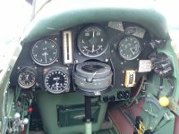
AVRO pitch indicator gauge - question???

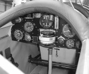
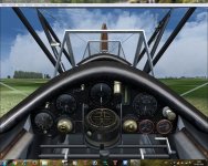
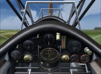
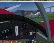
Until now the AVROs have been using the default Vickers Vimy pitch indicator in the VC cockpit. However, I'd like to take it a stage further towards authenticity and give the pitch indicator a better set of textures which may also assist better readings in marginal/poor lighting conditions.

attachment.php


attachment.php

Standard 'Vickers Vimy' Pitch Indicator

attachment.php

WIP textures for AVRO Pitch Indicator
 

Attachments

  • Tutor cockpit2.jpg
    Tutor cockpit2.jpg
    70.9 KB · Views: 3
  • pitch-standard.jpg
    pitch-standard.jpg
    96.9 KB · Views: 3
  • pitch-AVRO.jpg
    pitch-AVRO.jpg
    108.2 KB · Views: 3
Pitch Indicator gauge - texture question

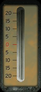
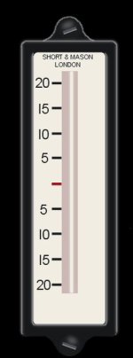
For the NEW textures to have the desired level of resolution and detail, I wish to create textures twice or more in size to the existing Vimy bmps (see attached).

attachment.php

Vimy Pitch indicator background bmp.

attachment.php

WIP AVRO Pitch indicator background bmp.

I have tried enlarging all 5 bitmap elements in proportion but the gauge no longer shows or functions as required. :-/

My understanding of XML gauges is poor to say the least - is there something in the coding that should change when going from 66 x 147 background bmp to 132 x 294 background bmp???

The gauge XML coding is:


<Gauge Name="pitch_indicator" Version="1.0">
<Image Name="pitch_indicator_background.bmp"/>

<Element>
<Position X="28" Y="12"/>
<MaskImage Name="pitch_indicator_liquid_window.bmp"/>
<Image Name="pitch_indicator_liquid.bmp"/>
<Shift>
<Value Minimum="-90" Maximum="90">(A:plane pitch degrees,degrees) /-/</Value>
<Nonlinearity>
<Item Value="90" X="29" Y="12"/>
<Item Value="23" X="29" Y="12"/>
<Item Value="20" X="29" Y="21"/>
<Item Value="10" X="29" Y="46"/>
<Item Value="0" X="29" Y="71"/>
<Item Value="-10" X="29" Y="97"/>
<Item Value="-20" X="29" Y="122"/>
<Item Value="-23" X="29" Y="125"/>
<Item Value="-90" X="29" Y="132"/>
</Nonlinearity>
<Delay PixelsPerSecond="115"/>
</Shift>
</Element>

<!-- ========================= Hightlight ===================== -->
<Element>
<Position X="28" Y="12"/>
<Image Name="pitch_indicator_highlight.bmp" Alpha="Yes"/>
</Element>

<!-- ========================= Shadow ========================= -->
<Element>
<Position X="28" Y="12"/>
<Image Name="pitch_indicator_shadow.bmp" Alpha="Yes"/>
</Element>
<!-- ======================= Reflection ========================== -->

<Mouse>
<Tooltip ID="TOOLTIPTEXT_SPIRIT_PITCH_INDICATOR"/>
</Mouse>
</Gauge>
 

Attachments

  • pitch_indicator_background.jpg
    pitch_indicator_background.jpg
    22.9 KB · Views: 6
  • pitch_indicator_background-new.jpg
    pitch_indicator_background-new.jpg
    39 KB · Views: 3
Edit. Just noticed that the symbols in the tooltip do not show correctly, so I have added spaces to see if it will now show correctly!
% ! 3 . 1 f & # 1 7 6 ; )

Sorry have not saved the .bmp as layered psd!
& now its wiped my original text!

Try again - (Dick Whittington?)
<Gauge Name="Inclinometer" Version="1.10" >


<Image Name="inclinometer#3.bmp"/>


<Element>
<Position X="107" Y="122"/>


<MaskImage Name="incwindow#3.bmp"/>

<Image Name="incliquid#3.bmp"/>
<Axis X="12" Y="374"/>


<Shift>
<Value Minimum="-20" Maximum="20">(A:plane pitch degrees,degrees) /-/</Value>
<Nonlinearity>
<Item Value= "20" X="106" Y="140"/>
<Item Value= " 0" X="106" Y="310"/>
<Item Value= "-20" X="106" Y="480"/>
</Nonlinearity>
<Delay PixelsPerSecond="100"/>
</Shift>

</Element>


<Mouse>
<Tooltip>Inclinometer (%((A:plane pitch degrees,degrees) /-/)%!3.1f°)</Tooltip>
</Mouse>


</Gauge>

Looking at the photo of the cockpit it looks as if it is a Short & Mason instrument. I first used it on my Miles M13 Hobby, but also on later ones e.g. Percival Gull.

Milton has a good description of the set up.
Keith
 

Attachments

  • inclinometer#3.jpg
    inclinometer#3.jpg
    13.8 KB · Views: 0
  • incliquid#3.bmp
    26.4 KB · Views: 0
  • incwindow#3.bmp
    26.4 KB · Views: 0
Last edited:
For the NEW textures to have the desired level of resolution and detail, I wish to create textures twice or more in size to the existing Vimy bmps (see attached).

attachment.php

Vimy Pitch indicator background bmp.

attachment.php

WIP AVRO Pitch indicator background bmp.

I have tried enlarging all 5 bitmap elements in proportion but the gauge no longer shows or functions as required. :-/

My understanding of XML gauges is poor to say the least - is there something in the coding that should change when going from 66 x 147 background bmp to 132 x 294 background bmp???

The gauge XML coding is:


<Gauge Name="pitch_indicator" Version="1.0">
<Image Name="pitch_indicator_background.bmp"/>

<Element>
<Position X="28" Y="12"/>
<MaskImage Name="pitch_indicator_liquid_window.bmp"/>
<Image Name="pitch_indicator_liquid.bmp"/>
<Shift>
<Value Minimum="-90" Maximum="90">(A:plane pitch degrees,degrees) /-/</Value>
<Nonlinearity>
<Item Value="90" X="29" Y="12"/>
<Item Value="23" X="29" Y="12"/>
<Item Value="20" X="29" Y="21"/>
<Item Value="10" X="29" Y="46"/>
<Item Value="0" X="29" Y="71"/>
<Item Value="-10" X="29" Y="97"/>
<Item Value="-20" X="29" Y="122"/>
<Item Value="-23" X="29" Y="125"/>
<Item Value="-90" X="29" Y="132"/>
</Nonlinearity>
<Delay PixelsPerSecond="115"/>
</Shift>
</Element>

<!-- ========================= Hightlight ===================== -->
<Element>
<Position X="28" Y="12"/>
<Image Name="pitch_indicator_highlight.bmp" Alpha="Yes"/>
</Element>

<!-- ========================= Shadow ========================= -->
<Element>
<Position X="28" Y="12"/>
<Image Name="pitch_indicator_shadow.bmp" Alpha="Yes"/>
</Element>
<!-- ======================= Reflection ========================== -->

<Mouse>
<Tooltip ID="TOOLTIPTEXT_SPIRIT_PITCH_INDICATOR"/>
</Mouse>
</Gauge>

Nigel,

This is likely simpler than it looks.

To help your understanding, open the Vimy background bmp in Paint ... yes, Paint or MSPaint or any program that will show pixel coordinates for your pointer.

These values represent the pixel coordinates on the background bmp, x, y. The first is the value on the bmp, then the x,y coordinates. You are telling the sim where on the bmp these values are found in pixel locations.

<Nonlinearity>
<Item Value="90" X="29" Y="12"/>
<Item Value="23" X="29" Y="12"/>
<Item Value="20" X="29" Y="21"/>
<Item Value="10" X="29" Y="46"/>
<Item Value="0" X="29" Y="71"/>
<Item Value="-10" X="29" Y="97"/>
<Item Value="-20" X="29" Y="122"/>
<Item Value="-23" X="29" Y="125"/>
<Item Value="-90" X="29" Y="132"/>
</Nonlinearity>


In Paint, find the X, Y coordinates:
<Item Value="0" X="29" Y="71"/>
with your mouse pointer, then look at the coordinates Paint has at the bottom.
Compare that to the XML values for Item Value ="0".
Adjust your mouse pointer to the xml coordinates:
<Item Value="0" X="29" Y="71"/>
You will then see where these numbers come from.
Do this for 10, 20, 30 positive and negative.
You should now understand how to adjust for the larger bmps.

Since your bmp is larger, the center location X="29" of the indicator will move farther right so you will need to adjust all occurrences of that and for the pitch indicator liquid, highlight, and shadow bmps.
<Element>
<Position X="28" Y="12"/>


You need only to worry about these values; I think everything else will fall in place.

If you would like a video, just say so. :)

Milton: Thank YOU for making perfect sense, Sir - you have explained it beautifully crisp, and clear (as always) :)

VIDEO: Now that is always a great temptation, Sir - have to admit to being an avid IFRfun subscribed fan of your amazing series already. :)
For my part, you have already explained the subject perfectly - but I'm sure a video for others would save hours of head scratching - threads tend to get buried away when you most need the Information...

https://www.youtube.com/channel/UCC3d0fWzoRK0eZv1Az7VqaQ

Those, and the private videos you kindly made before the public series are a Godsend - Thank YOU. :)
 
Again its really amazing to see the level of detailing you are adding to these beautiful models.

Cheers,
Huub
 
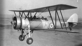
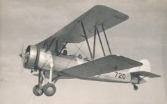
This is all I could find regarding the Avro Tutor in South African Air Force service: (info from the SAAF Museum, Ysterplaat, Cape Town)
51 built, 50 written off charge, 1 to technical training. There was 39 at the beginning of 1939.
Serial batches: 701-751

It started off with a 215-240hp Armstrong Siddeley Lynx IV C engine, & when spares ran out, a number were fitted with uncowled Wright Whirlwind engines.
The Tutor was choses to succeed the Avro 504N in the RAF's training schools in 1932, & a total of 394 were built for the RAF.

As a result of a tour of South Africa by Alan Cobham's flying circus & trials by the SAAF, with one of his Tutors, G-AARZ, the Tutor was selected to replace the Avian IV M for SAAF training.

Following the delivery of two Avro built Tutors, a production batch of Tutors was built under license at the Aircraft and Artillery Depot at Voortrekkerhoogte (Roberts Heights) in Pretoria.

The total of 51 is thought to possibly exclude a few more built from spares at the end of the program, & which carried serial numbers of aircraft already written off.

They were used pre war by the Central Flying School (CFS), (established at Zwartkop Air Station in1932) & continued in service mainly with 62 Air School (62 AS) in WWII, with a few issued to other units.

Only one Tutor eventually survived in South Africa & this aircraft, 721, was preserved by the SA War Museum.
It was unfortunately scrapped in the mid 1950's, & the only Tutor is preserved at the Shuttleworth Collection at Old Warden in the UK.

I could not find any colour pictures, but the museum curator advised that they came in silver & yellow.
The only information I could find regarding roundels is from decals..


86317_0.jpg


Interesting history there, Robin - Thanks - very much appreciated. :)

I'm sure we'll be able to deck-out a nice SAAF livery.

Funny you should mention the Avian; Initially I was going to include it within this Project (the early 621 shared various common structural components with the Avian e.g. tail/rudder). I now believe the AVRO Avian would make an interesting future Project.
 
Avian......Dave Molineaux has beaten you to that one - over at flightsim....with loads of repaints by Peter Watkins.
 
It was fun trying to find info. The library at the Ysterplaat (Brooklyn as it was called in the war years) Air Force Base has just gone through a revamp process & there is no index at all for the books, so it was a challenge trying to find information.
When I asked Barry, the acting curator, about the Tutor, he went blank for a moment, you could actually see gears turning, & he led me straight to the book.

Thanks, again,
Robin
 
Keith's Miles M13 Hobby, and an inclinometer favour...

Avian......Dave Molineaux has beaten you to that one - over at flightsim....with loads of repaints by Peter Watkins.

LOL Oh well, can't win 'em all I suppose... :wiggle:

Anyway; to continue Saturday's discussion on a NEW pitch indicator (inclinometer as I have since learned:) for the AVROs, I couldn't resist Keith's suggestion of the Miles M13 Hobby's inclinometer. So I took that pretty little Hobby on a circuit, or five (lovely little aircraft).

attachment.php


attachment.php


attachment.php


Yup, no two ways about it - much better gauge than that of the Vimy, and with fewer components and larger bmp setup to boot.

So here comes the question, Keith: Would you give me your kind permission to use the gauge (with NEW textures) for the AVRO fleet? :wavey:
 

Attachments

  • -2018-may-14-001.jpg
    -2018-may-14-001.jpg
    61 KB · Views: 4
  • -2018-may-14-002.jpg
    -2018-may-14-002.jpg
    68 KB · Views: 4
  • -2018-may-14-004.jpg
    -2018-may-14-004.jpg
    58.4 KB · Views: 3
It was fun trying to find info. The library at the Ysterplaat (Brooklyn as it was called in the war years) Air Force Base has just gone through a revamp process & there is no index at all for the books, so it was a challenge trying to find information.
When I asked Barry, the acting curator, about the Tutor, he went blank for a moment, you could actually see gears turning, & he led me straight to the book.

Thanks, again,
Robin

Robin, I believe this must be our Central Flying School, (Bloemfontein) gal. :)

I'm putting my Money on Silver - what do you reckon?

attachment.php


attachment.php
 

Attachments

  • 800x450.jpg
    800x450.jpg
    51.6 KB · Views: 3
  • f45_jpg_opt836x524o0,0s836x524.jpg
    f45_jpg_opt836x524o0,0s836x524.jpg
    53.5 KB · Views: 3
LOL Oh well, can't win 'em all I suppose... :wiggle:

Anyway; to continue Saturday's discussion on a NEW pitch indicator (inclinometer as I have since learned:) for the AVROs, I couldn't resist Keith's suggestion of the Miles M13 Hobby's inclinometer. So I took that pretty little Hobby on a circuit, or five (lovely little aircraft).

attachment.php


attachment.php


attachment.php


Yup, no two ways about it - much better gauge than that of the Vimy, and with fewer components and larger bmp setup to boot.

So here comes the question, Keith: Would you give me your kind permission to use the gauge (with NEW textures) for the AVRO fleet? :wavey:


Nigel, you are more than welcome, & to breath your magic in creating new textures. I have only found 1 good photo of a Short & Mason inclinometer fitted to a Tiger Moth and a few B+W adverts from Flight Global. My memory is not sure of the colour of the fluid that was in the instrument in my fathers tool box - it might have been flourescent green/yellow similar to radiator anti-freeze.
Glad you enjoyed the M13, found the RAE Flight test report thanks to the librarian at FAST Museum.
Keith
 

Attachments

  • tiger DSCF0042.jpg
    tiger DSCF0042.jpg
    111 KB · Views: 3
Nigel, you are more than welcome, & to breath your magic in creating new textures. I have only found 1 good photo of a Short & Mason inclinometer fitted to a Tiger Moth and a few B+W adverts from Flight Global. My memory is not sure of the colour of the fluid that was in the instrument in my fathers tool box - it might have been flourescent green/yellow similar to radiator anti-freeze.
Glad you enjoyed the M13, found the RAE Flight test report thanks to the librarian at FAST Museum.
Keith

Many thanks indeed, Keith - I'll send you a copy of the textures should you wish to make use of them also. :encouragement:

I have at least 1 reasonably clear photo of the Tutor instrument panel indicating red liquid. As this makes for good visual clarity I'll probably end up going for red.
 
Laying down NEW textures for Keith's Inclinometer - must say it makes the world of difference to in-flight pitch reference.
So far, the basics are in place; now for some fun with light, shade cast shadows etc.

Night panel lighting will have to be adjusted for a little less intensity, too...

attachment.php


attachment.php


attachment.php
 

Attachments

  • inclinometer_01.jpg
    inclinometer_01.jpg
    88.8 KB · Views: 3
  • inclinometer_02.jpg
    inclinometer_02.jpg
    100.5 KB · Views: 3
  • inclinometer_03.jpg
    inclinometer_03.jpg
    57 KB · Views: 3
Last edited:
Back
Top