-
Please see the most recent updates in the "Where did the .com name go?" thread. Posts number 16 and 17.
-
IMPORTANT DOWNLOADING INFORMATION - ALL MEMBERS PLEASE READ
Please see this thread for updates. Update Thread
SOH ADMINISTRATION
You are using an out of date browser. It may not display this or other websites correctly.
You should upgrade or use an alternative browser.
You should upgrade or use an alternative browser.
As the nature of things progress...
- Thread starter nigel richards
- Start date
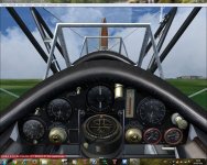
Laying down NEW textures for Keith's Inclinometer - must say it makes the world of difference to in-flight pitch reference.
So far, the basics are in place; now for some fun with light, shade cast shadows etc.
Night panel lighting will have to be adjusted for a little less intensity, too...


Wow, another improvement in the works, the bar is still being raised!
nigel richards
Charter Member
Just outstanding! I'm ready when you all are. I recently found my way back to the origination of this project some two years ago, as it is spelled out in this thread. The amount of effort by so many talented people is impressive.
downwind: Thank YOU Sir - Check your PMs.
")
Wow, another improvement in the works, the bar is still being raised!
Pleased you like it, Sascha66 - Bar is OPEN!


Motormouse
SOH-CM-2025
Couldnt help but notice that the RPM gauge is canted over on this one.... so before anyone complains to Nigel, I believe I can elaborate why...
Pilot's (and us engineers) are taught to scan instruments, rather than spending time closely examining them so we can maintain our situational awareness when operating the aeroplane and its engine / systems.
In this instance the orientation of the Rpm gauge is such that the needle will point to a particular clock position, at a particular RPM setting ie for example 2000 RPM = 3 O'clock, making it easier when scanning instruments.
The RPM gauge itself, doesn't care which way up it is, it just indicates RPM, but if setting aeroplane up say for aerobatics, its a quick way of checking RPM is correct, see which way needle is pointed.
It's an 'in service' alteration if you like.
Ttfn
Pete
nigel richards
Charter Member
Couldnt help but notice that the RPM gauge is canted over on this one.... so before anyone complains to Nigel, I believe I can elaborate why...
Pilot's (and us engineers) are taught to scan instruments, rather than spending time closely examining them so we can maintain our situational awareness when operating the aeroplane and its engine / systems.
In this instance the orientation of the Rpm gauge is such that the needle will point to a particular clock position, at a particular RPM setting ie for example 2000 RPM = 3 O'clock, making it easier when scanning instruments.
The RPM gauge itself, doesn't care which way up it is, it just indicates RPM, but if setting aeroplane up say for aerobatics, its a quick way of checking RPM is correct, see which way needle is pointed.
Ttfn
Pete
Fascinating insight - Thanks Pete
I would have liked to have matched that canted RPM gauge, but it would have involved entirely NEW xml coding as far as I know.
If someone has the will and expertise to handle the coding, I'd happily go for texture changes and installation.
Interesting having a canted meter.
My Alfa car had that, so, as a certain speed, both the rev counter needle & speedometer needle were both vertical... We called that 'goalposts' & we had a great indicator of what was happening with just a quick glance. We did not have to read the 2 meters.
My Alfa car had that, so, as a certain speed, both the rev counter needle & speedometer needle were both vertical... We called that 'goalposts' & we had a great indicator of what was happening with just a quick glance. We did not have to read the 2 meters.
Fascinating insight - Thanks Pete
I would have liked to have matched that canted RPM gauge, but it would have involved entirely NEW xml coding as far as I know.
If someone has the will and expertise to handle the coding, I'd happily go for texture changes and installation.
Looking at your gauge coding - simplest thing is to rotate the .bmp image & place it on another background that is square upright -if you get my description. Next stage will be to redefine the X & Y positions to correspond with the required calibration points - simples? If stuck will do it for you!
Re: 'my' inclinometer it is now yours my friend as I do not hold copyright on the coding & very fine it looks too.
Keith
nigel richards
Charter Member
Looking at your gauge coding - simplest thing is to rotate the .bmp image & place it on another background that is square upright -if you get my description. Next stage will be to redefine the X & Y positions to correspond with the required calibration points - simples? If stuck will do it for you!
Re: 'my' inclinometer it is now yours my friend as I do not hold copyright on the coding & very fine it looks too.
Keith
Thanks Keith - 'our' inclinometer is now more or less serviceable.

Revised AVRO RPM gauge bitmap in place (Thank heavens for PSD layered 'motherfile').
Time for a quick infusion of fresh coffee bean juice, then onto pointer calibration.
Attachments
One comment though Nigel. There are two engines used, one the Mongoose, I think cruises at 1600 rpm, & the Lynx I think sits at 1800 rpm. Now from my point of view I would think the dial would be aligned so that those RPM's were vertical to make scanning easier to recognise?
Sorry nitpicking - will go back to sleep!
Keith
Sorry nitpicking - will go back to sleep!
Keith
nigel richards
Charter Member
One comment though Nigel. There are two engines used, one the Mongoose, I think cruises at 1600 rpm, & the Lynx I think sits at 1800 rpm. Now from my point of view I would think the dial would be aligned so that those RPM's were vertical to make scanning easier to recognise?
Sorry nitpicking - will go back to sleep!
Keith
Good point, Keith...then there's the Wright J-5 hitched to the PWS-18.
That's not nitpicking.
Sleep?
Coffee's fine, young man!
EDIT: Then there's the Prefect's Cheetah...Bugger!
Good point, Keith...then there's the Wright J-5 hitched to the PWS-18.
That's not nitpicking.
Sleep?
Coffee's fine, young man!
EDIT: Then there's the Prefect's Cheetah...Bugger!
Put it back - that makes it generic.......Which it probably was when built!
Keith
Bushi
Charter Member
Put it back - that makes it generic.......Which it probably was when built!
Keith
Easier than a dedicated panel for each engine variant!
Dave
nigel richards
Charter Member
Put it back - that makes it generic.......Which it probably was when built!
Keith
Easier than a dedicated panel for each engine variant!
Dave
Yes, I'm inclined to agree, Gentlemen - think we'll go with what we have on this after all.
Motormouse
SOH-CM-2025
Yes, I'm inclined to agree, Gentlemen - think we'll go with what we have on this after all.
Yikes... didn't mean to start all this
Ttfn
Pete
nigel richards
Charter Member
Yikes... didn't mean to start all this
Ttfn
Pete
Pete; LOL, I'm pleased you did - it's exactly the kind of input that makes these projects come alive.
Tilted looks great.. gives a bit of character, & is a bit different.
Okay Robin - maybe we'll go with just one engine version - the Lynx-engined Tutor would be probably be my personal choice...
Gentlemen?


Motormouse
SOH-CM-2025
Pete; LOL, I'm pleased you did - it's exactly the kind of input that makes these projects come alive.
Okay Robin - maybe we'll go with just one engine version - the Lynx-engined Tutor would be probably be my personal choice...
Gentlemen?
Whatever you decide Nigel , its' your project
ttfn
Pete