Learning AD2K

dealing with tedium is one thing,
danging one's head against the wall,
trying to find a solution is something all together.
i've spent most of the day in the attempt,
with no positive results...that's frustrating.
i guess relearning the simple facts
of visual sequencing can be considered a positive.

after that lesson, i decided to move
the gear SA out the wing...no problem.
BUT, now the vectors are misaligned.
so, i screwed around with that for a while,
eventually realizing, i can't remember how to do it.

i'm going to set it aside for a while.
i gave myself a headache.
 
Hello Smilo,
Oh, deary me!, as our junior school english literature teacher used to say.
I am terribly sorry!


Actually, my initial design mod involved a higher propeller and the normal length landing gear, with a nose that was less slanted on the top than at the bottom. Unfortunately the unmodified vector then made the prop wobble - I wasn´t conscious that the vector would have to be translated upwards to fit the centre of the higher propeller.

That would in fact have also been a good solution, and could be easier than moving the gear outwards.

Please don´t torture yourself any more - the job done is wonderful, and I myself have to fix the misalignement in one way or another!

Cheers,
Aleatorylamp
 
torture, shmorture...don't be sorry.
this is an investigation process
for myself as well.
as i told you, way back there,
i don't do things, i don't want to do.
at this point, it's become a challenge.
i will not be thwarted.
...not yet, anyway.
actually, i'm working on it right now.
 
Hello Smilo,
Well I´m relieved that this is the case, and not what I´d feared!
So then, just to get my bearings, the plan is shifting the gear outward.

Now I remember the reason for the simplification of including the Skirts
with the Gearstruts: There was a Skirt hinge problem from the start,
whereby the WDOOR R0y instruction given in the tutorial for the Skirt
hinge was never accepted, automatically forcing the use of WDOOR R0x,
despite there being another vector defined for it, close to the Gearstrut one.
This made the skirts hinge backwards, and not inwards after the Gear!
Strange...

Update:
OK, so I´ve taken the Gear asub-assembly into multiple selection to shift it outwards
by 2.5, and it´s sitting now at 13.5.
Then I edited the vector, changing it by 2.5, to move it outward from 11.0 to 13.5, and
it accepted it, although initially it seemed to be off centre before pressing confirm and
validating with OK. It seems to accept it, but after compiling the model, the vector used
is still the old one, and the retracted gear is too low and inwards, apparently 2.5 ft off.
Investigating in the Model Editor, there is only one vector at -13.5 to choose from, and
none at 13.5,
so now the right gear tucks in at wing height but still 2.5 inwards - no good!
So the initial offset of this vector that appeared while editing it messed things up.
Let´s see......

Cheers,
Aleatorylamp
 
Bingo! The movement is perfect.

Hello Smilo!
But only the movement. The display is ALMOST perfect.
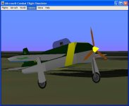
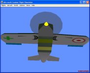
When I went to made the opposite vector on the right at 13.5, I still couldn´t find it to assign it in the Model Editor, so I wanted to edit it, and suddenly the old vector at 10.5 appeared selected for editing, and I entered 13.5. Going to the Model Editor to assign it, it suddenly appeared as 13.5. I compiled, loaded the model into CFS, and it works!! The gear shows perfectly lined up, tucked in, in its place when retracted and doesn´t look bad at all.

I´ve attached some screenshots. You will notice by the shadows, that the .air file still needs adjustment, but we aren´t working on that yet...

Looking at the way the gear strut now disappears flush disappears within the wing (I didn´t have to do anything here, it corrected itself), it is probably best not to include the strut with the retracted gear position just the skirt and the wheel so that it won´t bleed through the wing leading edge. Then, possibly the skirt could have a slightly darker shade from the rest of the wing, just to make it show.

Update: I was trying to make the strut polygons hidden when retracted, but there´s only one instance for them, so it´s impossible to do in an easy way.

To post the current version will be better when the plane is definitely finished, so that it is posted as a tutorial together with the Plane Jump Refresher Guide you are preparing, unless you want to see the file now.

I also want to do the turning wheel experiment, with the intention of including it in the tutorial because of its unique feature for CFS1.

Cheers,
Aleatorylamp
 

Attachments

  • MCubFly2-1.jpg
    MCubFly2-1.jpg
    39.4 KB · Views: 0
  • MCubFly2-2.jpg
    MCubFly2-2.jpg
    35.6 KB · Views: 0
Last edited:
remember how i said, i was backing away?
wrong...i puttered on it for the rest of the day,
got a loose grip on vector editing,
and changed mine to 13.50, 00.00, 00.90
and -13.50, 00.00, 00.90 on the left side.
i also used multiple selection to shift the gear SA outward.
funny how we did the same thing
and got the same results...success.

i am still perplexed by the retracted strut
bleeding through the wing edges.
i am seeing it briefly fore and aft.
as far as i'm concerned,
this is not acceptable.
the has got to be a way to cure it.
i will continue to try to figure it out.

at this point, i am leaning toward,
manually rotating the strut
into the retracted position,
then, figuring out how to make it disappear
from all points of view.

it seems to me, figuring this out is critical
for any model with retracting gear.
...doesn't it?
 
Hello Smilo,
So you remembered and finally did it. Great! That is even more relieving to know.

You have also come to the same conclusion. The way the vectors and parts all line up, indicates to me that the strut has to be separated. Rotate the strut separately... as it´s not connected to the skirt and wheel it may stay hidden above the seal?

From what I have been able to learn so far, one can´t escape from having to set up a separate sub-assembly for the strut. Would setting up a glue sequence within the Gear sub-assembly be any good to hide the strut seen from fore or aft through the wing leading or trailing edges?

There should be a way of just not showing the strut when the gear is retracted... but perhaps only in a real animation.

Perhaps one could maintain the skirt on the same hinge, and not convert it into a different-moving well-door, because the strut retracted strut remains above the seal and will probably disappear by itself. If not, it will have to be treated like a door, like it says in the tutorial. I wonder if the R0y rotation will be allowed . Maybe it was because of a non-existing vector? I don´t know.

One could maybe also have a black gear-well appear with the extended wheel... that would be a black copy of the skirt plus a black copy of the wheel... but that is just further speculation and doesn´t have to be done if it´s going to mean even more complications with seals.

Update: Plan B. Very simple: Use the present set-up, but a lower hinge and retracted position.
There is a Polish utility aircraft and crop duster, like a little brother of the Air Tractor. It comes with a neat optional retractable landing gear.
A light-weight pneumatic mechanism run by a compressed air bottle is good for quite a few retractions. Gear extension is by gravity and spring blocked. The curious thing about it is that there is no wheel well: The retracted gear rests horizontally against the under-wing surface, with a fairing or skirt that covers the strut and half the wheel and has a frontal aerodynamic flange that fits flush to the wing.
So... all we have to do is put a flange on the skirt and change the hinge position a little inward so that the gear rotation leaves the whole gear unit under the seal.

Then, looking at the subject of the rotating wheels, wheels would have to be separated from the l/r Gear Sub-assemblies as well. The standard AD2k WHEEL ROT process cannot be used because it only works for FS2000 and CFS2,but, forFS98 and CFS1 it can be "trans/rotted" by 1 degree.


As far as I can see, perhaps it could be possible to display all these separate sub-assemblies within the currently existing Sequencing procedurewithout the creation of additional seals.

Well, at least we are getting somewhere slowly! It is definitely interesting and fun. When I saw how nicely the model fit together after your sequencing, although I was expecting it, it felt absolutely fantastic!

Anyway, I always say "anyway", and I always say
:ernaehrung004:,
Aleatorylamp
 
Last edited:
after going back to bed early this morning,
i laid there thinking about it.
i remembered a project i did long ago.
it was an A20 with gear that retracted into the nacelle.
as i recall, it was a tight fit.
i had to keep adjusting because,
if i wasn't careful aligning it just right,
the tire would protrude through
the top or bottom of the nacelle.

okay, so what?

so, that tells me, there is a way
to get the gear to disappear inside
AND it tells me there is a way
to get part of the gear to protrude.
all i have to do is remember how to do it.
or, dig around and find the old A20
and copy the sequence.
there is hope.

now, for some coffee.
 
Good morning, Smilo, and good late afternoon to me!
Enjoy your coffee, I´m just going to make my afternoon tea!
Interesting once again.
Your rememberance of the A20´s gear disappearing inside a nacelle is a clue for the possibility that a Strut made as a separate Sub-assembly, moving together with the Skirt and Wheel panels in their own Sub-assembly, would be invisible inside the wing.
I´ll go for it and see what happens!
Cheers,
Aleatorylamp.
 
i've found the old A20 project.
there are an untold number
of 3DM and 3DMI files and folders.
not to mention, numerous cfs models.
(at the time, i would produce a new model
for each and every section of the aircraft.
i would build at 0, 0, 0 so the compiled section
could be easily viewed in cfs**)
it's almost overwhelming.
the current task is wading through them all
and finding the cfs model with the accurate retraction gear.

**speaking of viewing in cfs,
is there an easy way to slow the roll rate in the air file?
i like to view a model in slew mode,
stationary, at altitude, but, rolling.
then, view it from different view angles.
if the roll rate could be slowed to a crawl,
it would be very helpful.
 
Hello Smilo,
Good Grief! It´s like rummaging in the attic!

Your description of the A-20´s wheels portruding through the nacelle if not exactly fitted, sounds like it was for FS2002, with its "superior" Z-Buffer-equipped 3D machine.


I got a dizzy trying to figure out how to alter the Jump Plane calls in the Gear Sub-assembly and the Main Assembly, if I take the Strut out into a different Subassembly, or do the same with the Wheels make them turn, and had to give up.

So, I have changed tactics for the moment, to have an external Gearwell-less pneumatic+gravity driven retracting Gear, like on the Polish utility plane/Crop Duster. If it works properly, I´ll make a fairing for the skirts.

In a previous post you mentioned your LG hinge vector as having changed to 13.50, 00.00, 00.90 and -13.50, 00.00, 00.90. I would have thought raising the axis by 0.9 would cause the 90-degree turning gear to move further into the fuselage and shine through from the top.

At the moment I´m trying out lowering the hinge to -.9, to get the whole subassembly below the seal and to get the wheel further away from the fuselage. I´ll see how it works. For the moment it´s not letting me edit whole the vector height, only one end, making the wing bend down. Making a new vector is not recognized either. Not everything is as easy as it seems...

Good luck with your searches!
Cheers,
Aleatorylamp
 
i completely understand the dizzying factor.
sometimes, you just have to walk away for a bit,
gather your thoughts and jump back into it.

i have spent, i don't know how long,
going through both, cfs and ad2k, a20 files.
(there are, no doubt, more on other hard drives)
anyway, i have been unable to find
the bleed free gear/nacelles i'm looking for.
now, i'm wondering if it was a dream.

while i was digging around i found
an original MYRFO 3DM file.
i opened it in ad2k and noticed
-the wheel and strut
-and the skirt
are in two separate SAssemblies per side.
not that it really matters,
there are no jump planes sequences
so, everything is a bleeding mess.
but, i found it interesting.

about the +- 00.90 vectors entries,
i did that to get the gear point i
centered inside the wing,
so, when retracted,
the strut would be buried in the wing,
but, the skirt would be flush with the wing bottom.

okay, i'm off to look through some more a20 files.

hmm, a curious thought...
since the model is more complex,
how does the ugly100 deal with the gear?
 
STAND-BY!!!
preliminary tests are positive,
i may have it.

still need to bury the strut
and look again.
 
Hello Smilo,
Very interesting, very interesting indeed...

The Hinge position on the Gear with the Skirt together on the Cubefly, is also suposed to achieve the same effect, because it hinges on the skirt rather than on the strut, and the skirt ends up flush with the wing under surface.

Yes, the authentic RFO has separate assemblies, because the Skirt is actually a wheel door.

The Ugly100, (and the Pony) have a different Gear Rotation which is progressively animated - it used JUMP GEAR and RANGE. The range goes to 228, which may be -132 Degrees (360-228) , but for my liking the gear disappears much too soon.
If all fails, the CubeFly could also get such a gear no prob!

Anyway, I´m very intrigued with your preliminary tests, and wish you luck!
Stubborn as we are, the tutorial MUST be adapted 100% for CFS1 if at ALL possible!

Cheers for the moment!
Aleatorylamp
 
when i scan views around the wing,
there are no bleeds with gear retracted.
oh joy!!

BUT, as i roll the wing in slew,
viewing from different angles,
i still see the embedded strut bleeding
through the leading and trailing edges.
for a few minutes, i really thought i had it.
i'm not giving up, though,
i still have a few ideas to try.

sorry for the false alarm.

about the tutorial,
if it was me,
i'd hold off until we have it down pat.
i mean, it's okay to update it,
but, folks might get tired of downloading
incorrect information.
once again, just my opinion.
 
Hello Smilo,
It has just dawned on me, that as the RFO tutorial is for FS2000, we may be barking up the wrong tree.

Even by separating the Strut into a different assembly, we don´t seem to be any better off than yesterday with the strut in the same sub-assembly as the skirt.

Now that we have done s much work trying to use Trans/Rot, we could show the gear tucked under the wing a bit below the seal by lowering the hinge vector (I actually quite fancy this idea).

The alternative is changing the instruction to retract the wheels. CFS1 requires the gear not to be displayed just when it reaches the wing undersurface, and TRANS/ROT can´t do it.

What´s there, is what there is. "Es lo que hay", as they say here!

Section 5 in Tutorial 98 for the Ugly100 deals with this clearly, using JUMP GEAR + RANGE 228,0 and then GEAR BANK + VECTOR. The Gear Sequencing is in the left and right Wing Assemblies. I suppose one could enter maybe 240 so as not to make the gear disappear so soon.

OK. Then, Good Night!
Cheers,
Aleatorylamp
 
well...isn't that special?
i'll give it a try.

after hours of little or no success,
i finally decided to dump it all.

actually, i made a new SA called BOX.
it is a rectangle large enough to hold
the strut with plenty of room to spare.
each side is a GPOLY of a different color.
the purpose of this exercise is to see
if i can get the strut to completely disappear
inside the damned box when viewed from all angles.

as i said before, this is an important problem
to solve before moving on to another phase.
besides, it's pissing me off and i can't let it go.

too funny...woof
 
one last bark up the tree

Hello Smilo,
Ha ha! Woof! I had to laugh. But anyway... That´s told the tree!

So it looks like we have the following choice: The Crop Duster´s externally retracting gear with a flanged skirt and no wheelwell, or the animated sequence from the Ugly100.

The first could be didactically better as it illustrates another way of doing things and also because the second is in another tutorial anyway, but... the second one would be more professional aircraft-builder-wise, but it is realistic as it does exist.


Hey! I´ve just had an idea. I can´t leave it either because it´s also pissing me off. So, just to be obnoxious...

One last bark up the tree:


The text regarding turning wheels (I have attached it herewith, it´s only 2 pages long and in large font), explains the theory very well, including and separating both concepts, the Turning of the Wheels and the Retraction of the Gear. Here is an exerpt from the text, regarding Gear Retraction:

QUOTE

Gear movement (for both the gear strut and the wheel)
We have to perform the following operations:
1) a translation to move the center of rotation of the gear to the origin,
2) the rotation of the gear,
3) a translation to move back the gear.

UNQUOTE

Now: Assuming we write another separate SA where just the strut polygons are HIDDEN,
and we add these two following things to the Gear Movement concept:

4) a second translation to move the new strut SA to the centre of rotation of the gear to the origin,
5) the hiding of the struts with all the polygons marked as HIDDEN.

The question is, would this be possible to do?
... or, is this what you were trying to do all along and it isn´t possible?

Cheers,
Aleatorylamp
 

Attachments

  • wheel rotation.doc
    32.5 KB · Views: 0
hello Stephan...my brain is mush.
this was my last look before going to bed.

i searched and found an old copy
of the ugly rightwing 3DM
and have been working at it all evening.
every time i think i've got it,
something jumps up and bites me in the a$$.
i can make the gear totally visible
when extended..no bleeds, perfect,
but when retracted...words can not express.
OR, i can make the gear totally invisible
when retracted...no bleeds, perfect,
but, when extended...bleed city.

i've had enough for the night,
but, will dive back in, in the morning.
i still have a few ideas
and the sequence you've posted adds another.

the rotating wheels looks interesting,
but, i'll leave that until after i complete this task.

as for the externally retracting gear with a flanged skirt,
i'd say go for it if you want to. it's your call.
personally, i'm locked in on the disappearing gear.

i'm off to bed...good night or morning as it were.
 
last bark no use either

Hello Smilo,
The mush brain syndrome is what I also have with this. I doubt that my last Idea will work.

I was trying to find another way of doing to do what you are trying too, i.e. hiding the strut when it is retracted, but this idea will not work because:
What´s the sequence I want to add really going to do? Translate an already hidden SA section to the origin to get it out of the way? It´s hidden anyway, and won´t affect the other SA that´s not hidden!
There seems to be no HIDE instruction that can be activated by the Simulator. You can only hide something permanently in AD2000 which is part of something you built that you don´t want to show.

From your current investigations re. animated gears using Jump Gear + Range, I´m surprised that a Jump Plane instruction cannot avoid bleeds.

I hope I haven´t opened a can of worms... But there MUST be something that can be done.

Well, something has to be done, so I´ll go for the externally retraction concept, just to finish off this tutorial.
Then I´ll move on finishing the second tutorial - only the front animated prop Assembly is still missing.

I looked at the Ugly100 gear retraction:
It´s quite clean and there are no bleeds between struts and wheels, but there seems to be 2 simplifications:
1) There´s no skirt, and
2) the movement arc is a bit limited.
Why? because of possible bleeds? Hmmmm... I wonder.
A wheel-door can of course be put on, with a vertical seal to separate it from the gear. There are separate instruction for Wheeldoors onm AD2000 anyway.

Well, I think one has to take it a bit easy.

Cheers,
Aleatorylamp
 
Back
Top