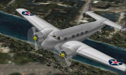
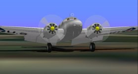
Lockheed Electra Model 10

Aleatorylamp said:
Your new glue sequence is rather unexpected, starting with the exhaust pipe,
moving inwards to nacelle and inner wing, and then outwards again to the outer
wing, finishing with the flap!

Hello Aleatorylamp,

Your reaction to the odd Glue sequence is pretty similar to Hubbabubba's reaction when he saw what I did to his Taifun and started using the term "Ivan's Conga".

If you are satisfied with the Flaps the way they are, I won't pursue it any further.
I don't think simply cutting off the top of the Flaps would be a good idea.
There are a few angles where the gap would be visible.
You would probably need additional Parts to block the gap.

- Ivan.
 
The Four-part Conga.

Hello Ivan,
Ha ha!
Yes, I´ll leave it be - it works very nicely now.

Thinking about it a little, it ties in with your discovery of the fact that a
glue-sequence does not have to be the usual way with each part having
only 2 parts glued to it. This would be "Mono-linear", like you did with
the Wing-Low
sequence: Wheel-well parts/tucked wheel/duplicated flap.

Your "Ivan´s Conga" mode, from what I saw upto now, allowed 3 parts, in a
left+right branching from a central stem. A central element can have one part
glued to the top of the list plus two parts (one each side)
at the bottom, totalling 3.

But in effect, it appears to be 4 glued parts in a sequence now!
The nacelle as a central part, with the exhaust at the top
and the wing sections
below on each side, making 3... BUT: W
hat gets me in this case, is the one-piece
flap glued
to the end. That would be a 4th part!

Anyway, now I´m going to figure out that disappearing window strut
because of the crew figure.

Then, I was thinking of following your suggested rounder wheel
cross-section, as components. It would mean twice as many parts, they
are available!

And then the difficult part: Turning the nacelle structures into components
with holes in the sides where the wings are attached.

OK then, it´s back to the grindstone!
Cheers,
Aleatorylamp
 
Hello Aleatorylamp,

Turning a Structure into a Component even with cutouts is incredibly simple.
If I were doing this, I would first create two template parts (not AF99 Templates) but more like construction fixtures to locate the inboard and outboard intersections with the Wings.

....and determine a naming convention for what is going to be a LOT more Parts.
After that, it is just a matter of snapping to the the vertices of the Structure and the template Parts.

I think the AF99 Glue discussion deserves its own thread at this point, so at some pont I will continue there, but just as a quick response:
I don't consider it so much as 4 way or anything like that. It is really (unfortunately) very much like a Vine in logical terms though maybe not so in spatial terms. There are many possible analogies which I will leave to a new thread.

No, the thread will not be named "Ivan's Conga".

- Ivan.
 
Hello Ivan,
Funny, I was just planning my strategy on how to go about a template
for the new nacelle component, but was getting into a twist including
upper and lower profiles too.

So: Thanks for simplifying my plan! Intersection vertices only, because
it
will be easy to build up towards the top and bottom profiles later!

I´m also very much looking forward to your new "Vine" Glue thread!

I suppose one of the things prior to starting it, would be to decide on
a
convenient model to illustrate the discussion, to be able to follow it
in a practical way.

For that thread I´d also a very specific question regarding the best glue
sequence for a twin tail whose fins are placed inboard of the tailplane tips.

Cheers,
Aleatorylamp
 
Hello Aleatorylamp,

Realistically, I believe it would take about 30 minutes to build a Component of nearly identical form to the Structure you are currently using for the Engine Nacelle. It is REALLY that simple!

The problem with this task as with any other is that I can't do something like this without refining it in some manner.
In other words: are the ends of the Wings shaped optimally to match the Nacelle? My guess is that they probably are not.
I usually spend a lot of time lining up the intersections between different pieces of the aeroplane and I don't know if you have done that or not because it is not really an easy thing with a Component intersecting a Structure.

I don't know if there is ever a "best" Glue sequence.
Complication sometimes confuses AF99.
If you want to see something pretty similar in appearance but more complicated, look at how the Fins / Stab were put together on my P-38 Lightning. THAT is a weird one, but it works!

I actually have no idea when I would begin a thread about AF99 Glue.

- Ivan.
 
Hello Ivan,
I had a look into your LightningJ that I had in safe-keeping. The twin tail/boom
IS certainly a very curious ensemble. As you say, it is much more complicated
than on the Electra, but eliminating the booms, the rest of the tail is a good
example of what I would need.

Re. nacelles.
I got the section behind the cowls working, and regarding the wing sections,
the vertices were already all lined up, but I can probably improve the shape
of the wing/nacelle joint, as per your suggestion.

It´s less complicated than I thought for a nacelle component. The shape of
the nacelle structure I was using required bending the joint-line into a steady
arc on both sides.

In reality, at the top, the inboard joint is a bit straighter, and the outboard
one slightly "S" shaped, so I´m putting it right and it´s not too confusing.
It might not be all that noticeable on the finished model, but it´ll be better!
We´ll see!


Cheers,
Aleatorylamp
 
Last edited:
Hello Aleatorylamp,

When I made the suggesting about looking at the P-38 Lightning, I was thinking that it was worthwhile to look at the thread abouit the model development here:

http://www.sim-outhouse.com/sohforums/showthread.php/90998-Lockheed-P-38-Lightning-Design-Study

The relevant stuff is on about Post#3 or somewhere around there.
The added complication for Lightning was because there was the Boom exgension into he Tail, so for me, it was costing about 4 Components per side. I figure your Electra doesn't have the rounded section in the middle, so it should only cost 3 Components per side or even less if you are working with Structures there.

The idea of reshaping the Nacelle was because the chances were pretty low that your Nacelle stations lined up with the Wing Spars.
With Low Polygon Modelling as we are doing here, I believe it makes for a better model with fewer bleeds if the Vertices from one piece line up with the Vertices from the adjacent piece.
If you can't do that, there should be a slight overlap but if the contours don't match, that would be rather difficult.

- Ivan.
 
New nacelle top!

Hello Ivan,
Thank you very much for your indications!

I understand that the P38 structure´s booms and supercharger elements, make
a greater complication than the Electra´s tail, so this should really be no problem.

As it is, I´ve already seen how I can eliminate the flaw whereby my left and right
taiplanes (grouped in Tail left/right) are bleeding through the nose when viewed
from head-on, by making a central tailplane section grouped in Tail, like you have
on the Lightning. That should do the trick!!

Re. Nacelle:
I was actually taking for granted that nacelle and wing-section vertices should
match! I´ve just done the nacelle-component top, with the visually corrected
joining-line, and it looks really fine!
Here´s a screenshot! ...n
ow comes the bottom part.

Re. ordering nacelle component parts:
The parts list starts with the inboard parts at the joint, then moves up/down
to the bulge, and finshes on the outside joint, where visual priority is highest.

When I finish the lnacelle-bottom, I´ll post another screenshot!
I´ll also line up the tailplane texture a bit better...
Thanks again, and cheers,
Aleatorylamp
 
Left and Right Tail Groups

Hello Aleatorylamp,

I forgot to mention this last time, but I would suggest you forget about the Left and Right Tail Groups entirely.

In order to use those Groups, you will need at least one more Component and while I can see needing to use those Groups when the assembly sequence gets complicated as it did on Lightning. (I HAD to start with the Fin on each side.) I believe in your case with Electra 10, you don't need that level of complication.
Just put everything into the Tail Group.= and things should work pretty well.

I believe that with the Left and Right Tail Groups, they will always bleed at certain angles. It is just a matter of how close you need o get before they bleed.

Putting everything into the Tail Group also addresses the bleed of the Tail Cone through the Stab Tips which I had also noticed but not commented on because it wasn't that bad and was a bit out of the scope of the contract.

- Ivan.
 
Electra WIP-4

Hello Ivan, Hello Smilo,
Well... Here´s the improved Electra: WIP-4 with a couple of pics.

Perhaps you would like to try it out - for Quality Control, as it were!
I wonder...

The engine nacelle bodies are now components, and fit much better into
the wing, with their vertices aligned with those of the inner and outer
wing sections. They also have fitted wheels wells.

Wheels are now also components, with rounded cross-sections, and
the tail empenage shape and sequencing has now been improved, although it
was impossible to fix without using tail left/right groups for the fins.

There are minor bleeds with exhaust/wing seen from above,
windshield/body seen from below, and flap/nacelle seen from the front.
Updated: I got the windshield bleed out by insignia-tagging it, so that´s
one problem fewer.

The textures correspond to the Army Air Corps.

It has been quite a bit more difficult that what I expected, but at least
the model has come out a lot better than before! Parts count is now at
148.6%, using 29 components and 18 structures.


P.S. There was a slight animation glitch in the WIP-4 attachment after
a landing-gear correction, so I´ve fixed it and
substituted it as WIP-4a.

Cheers,
Aleatorylamp
 

Attachments

  • new3.jpg
    new3.jpg
    29.9 KB · Views: 0
  • new4.jpg
    new4.jpg
    67.6 KB · Views: 0
Last edited:
WIP-4 no good

Hello Ivan,
Apparently the WIP-4 is no good, and I will have to re-work it.

I was trying to decypher the reason for the extended flaps bleeding forwards through the engine nacelle, when it of course wasn´t happening on the model you had corrected.

At first I thought it was because I had automatically glue-enabled the insignia-tagged Wheel Wells, that were not enabled for glue in your modifications, but that didn´t make any difference.

Then I decided to substitute the the old nacelle structure for the new nacelle component on the right side of your modified aircraft, and everything works fine! That put a hole in my things... Why is my build not working?

So, I thought obviously there is something I did wrong when I put in your modifications into my build. I checked the sequencing, but found nothing odd, so it had to be one or some of the glue templates I adjusted to fit to the new nacelle component.

I´ll just copy over all your ones again into my build, as they work on your modified model, and see what happens.

Update:I´ve just copied over all your glue templates, wheel wells and flaps included, but it still didn´t work on my build. I also re-checked the sequencing, with screenshots of the listing and setting them side-by-side, but it is identical.
The nacelle component is narrower below now, so the exhaust had to be moved inward - maybe it was that? I put in all the old exhaust parts again but it made no difference.
Very strange... I´ll continue my detective work and see what I can discover.

Update 2: I decided to use your modified model AFX, to continue using that and re-take it from there. I put in the new nacelle components, textured the model, and checked that it all worked on the right side. So far, so good.
I then transferred the modifications you had done on the right half of the model over to the left half, and strangely, the flap bleeds through the lower nacelle seen from the front, but only on the left side of the airplane.
Very strange: Completing your modified model, it´OK on the right but not on the left.
I wonder if this could be a useful indication...


Cheers,
 
Last edited:
Hello Aleatorylamp,

I saw this post very late last night but at about 1:30 AM, this system seems to be in a backup cycle or something that prevents any access. We were visiting my Daughter at school today, got home a couple hours ago and just finished dinner.
Although I do have Internet access via cell phone if I absolutely need it, I normally don't use that access for anything other than data that I need for whatever I am doing at the time. Today we were busy enough that there never was any time to check email or forums.

I saw that you posted a WIP version 4. Is that the version that you want me to look at?
If not, please post the AFX of the version you want me to look at.
Also post a few screenshots to show where you are seeing problems.

- Ivan.
 
Forward Flap bleed

Hello Ivan,
Thanks for your attention!
I hope your Daughter is doing fine at school.

Cellphones are a bit cumbersome for forum-posts, I agree.

Anyway, there´s really no hurry at all!

I´m stuck with the build. The previous couple of posts describe
the problem, and here´s a screenshot.

The last posted AFX WIP-4a would be the ones to work on.

To test
how it happens, completing your modified AFX on the left
side of
the airplane, with flap sequences and the new nacelle
components, also makes it happen -
only on the left side. Using
nacelle structures instead of the new components won´t make
any difference.

Then, exchanging the glue templates
that are just mirrored for
new left-side copies of the same to be
put in as regular instead
opposite, won´t help either.

Here´s 2 pictures. One of the textured model using WIP-4a, showing
the flap bleeds on both sides, and another picture,
un-textured and
using your modified AFX, completed on
the left, showing the flap-bleed
on the left.

Thanks for your help!

P.S. Then there´s a minor, momentary exhaust bleed - on the third
picture, but it´s by no means so important.

Cheers,
Aleatorylamp
 
Last edited:
Hello Aleatorylamp,

I am much less worried about my Daughter than about my Son.
My Daughter will do well. It is just a matter of how well balanced with how much stress she causes herself.

Attached is a minorly corrected AFX.
I believe what happened was that you did not notice that the extra Flap Part I added to the starboard side was an Insignia Part.
When you replaced it, you put in "Regular" Parts.

I did not have too much luck trying to correct the Exhaust Pipes on your Electra either.
I notice that you now have the following Resource Use:
18 Structures
29 Components
85 Parts
---------------
1189 Parts

What I noticed yet again is that you and I have radically different styles of building.
Some of it may be just differences of opinion and hopefully I don't push my own opinions on you, but there are a few changes I believe would make your building easier.

1. The choice of colour in an un textured model can help show up a lot of problems.
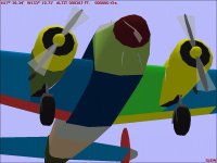
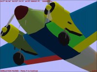
If you leave many pieces as "Group Colour", bleeds don't stand out quite as much.

2. Components are very limited and should be used where they significantly improve the shape or avoid a bleed.
I do not believe it makes sense ot use a Component for each of the Main Wheels or Tail Wheel, especially because there are other places that could use them more such as the Cockpit area or Tail.

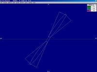
3. I believe your DF Loop would look better as a Structure than as two ring Parts.

4. I believe your Propellers would be much better done if they were aligned with either the Lateral or Vertical axis.
The Propellers should also align at least in Diameter with their Propeller Blurs; The Blades appear to be noticeably longer than the Blurs.

Attached are also some screenshots showing a couple problem areas as I see them.
I believe the Canopy Glass Parts just got flipped when you copied them from the other side.

- Ivan.
 

Attachments

  • ELECTR10.zip
    14.5 KB · Views: 0
  • PropMismatch.jpg
    PropMismatch.jpg
    27.5 KB · Views: 0
  • canopyGlassBleed1.jpg
    canopyGlassBleed1.jpg
    48.7 KB · Views: 0
  • NacellePanelMismatch.jpg
    NacellePanelMismatch.jpg
    48.5 KB · Views: 0
Hello Ivan,
Thank you for going through all the trouble, the repairs, the explanations and the suggestions.

So I´d missed something after all! That sounds more logical...

I´ll try and use colours that stand out more for the un-textured model to see the different parts and bleeds better.

Regarding our different building styles, I was actually trying to get the model closer to your style of building, but I seem to have missed some points. At least the nacelles have come out better as components now.

The wheels are now rounded as per your suggestion of not having Flintstone-type rollers, so I had to use components, but maybe I´m mistaken, and an oval cross-section would work, if parts count were to allow it.

I´ll try to get the propellers better.
What I do is make a prop circle as reference, an then shape it as a flat, vertical blade viewed from the front, and then rotate it to a) get the trailing edge further aft when viewed from the top, and b) get a tilted position so that it´s not horizontal or vertical, and is different from the one on the other engine.

Then, I try to get the prop blur shape aligned with the prop circle. The AA prop disc seems to have its size limitations - so I tried to adapt the blade sizes, but didn´t get it right after all.

I´m afraid I don´t see how to get the torus for a loop antenna by making a structure...

Anyway, I´ll start working on it and I´m sure I´ll achieve some more improvements.

OK, Thanks again!
Cheers,
Aleatorylamp
 
Hello Aleatorylamp,

As I see it, a little variety is good. Not everything out there should look like something from Ivan's Workshop.
....Life would be boring and there would be very few aeroplanes out there if folks were choosing projects like I do.
Yes, variety is Good.
I believe we each get carried away by our little obsessions.
I am stuck at the moment with the Macchi C.205 Veltro because I can't decided whether to alter the shape of the underside very very slightly to change the texture layout. This isn't even a stuck from a technical issue. It is a decision about what would look the best and to be honest, it isn't even really noticeable in the simulator even if I point out where to look.

As I see it, 1200 Polygons (more like 1175 as a practical limit) is a very tight limit on resources.
There WILL be compromises in shapes and detail and it is just a matter of how we can use what is available.
You do a pretty good job of that with your extensive use of Structures.
I simply can't stand the lack of flexibility that would result from using a Structure on a major piece of the aeroplane.
That is probably why you can push out more multi engine projects than I can.

Regarding "Stone Roller Wheels":
I believe that is just a consequence of developing with AF99 and its limited resources.
You probably saw this as a complaint when it was just intended as an acknowledgement of resource limits.
There are too few Components allowed in AF99 and I believe they should be used where they can most improve the shapes or reduce bleeds.
Sometimes, it makes sense to use one on a Wheel because a Component uses up fewer Parts than a Structure.
There is only one time I have ever thought that it made more sense to design a Wheel as a Component rather than a Structure and the reasons why should be apparent in the attached screenshots.

Regarding Propellers:
I have actually described the process I use to build what I consider fairly nice looking Propeller Blades, but the discussion was embedded in one of the other threads. If anyone is interested, I will gather a few screenshots and describe the process again in a new thread so it doesn't get buried. I just need to have a subject aeroplane that needs a new Propeller.
Perhaps I should try for a Hamilton Standard Propeller either for the FM-2 or P-47.

- Ivan.
 

Attachments

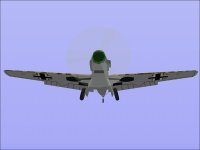
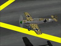
  • Me109E_ComponentTyres.jpg
    Me109E_ComponentTyres.jpg
    24.2 KB · Views: 0
  • Me109E_Flare.jpg
    Me109E_Flare.jpg
    48.7 KB · Views: 0
Much better!

Hello Ivan,
Of course, the slanted wheels on the Messerschmidt needed components.

In my case, it was only because the resource limit was far away that it
allowed three
round-cross-sectioned wheels with 50 parts per component,
but normally,
they would have been the typical square-cross-section wheel
structures.

If not rotated 15 degrees to have a flat surface on the floor, a 12-side-circle
"stone-roller" wheel structure consumes 22 parts. If rotated, only 17.
Then of course, if made into a component, it only consumes 14 parts, which
could be of help in cases of dire parts-count situations.

Usually, my fuselages have lots of structures, with top-only structures for
rounded roof sections, but the fuselage is all components on the Electra ,
except for the nose cone.

As you say, structures do help me get out of difficult parts-count situations
with multi-engined projects, for example, as happened with the Dornier-17
and the P3-Orion.

Actually, the Electra
is one of my models with fewest structures, only 18:

Spinners/propaxels and forward engine nacelles (6), crew heads and torsos (4),
nose cone (1), exhausts (2), tailwheel strut (1), and fin tops and bottoms (4).

At the moment, if I were to make the wheels as square-cross-sectioned
structures again, with the 1 component that´s left over at the moment,
I´d have FOUR free components and a few more parts to use elsewhere!

I´ll gladly do this if the 4 components would help anywhere, but I don´t
know where they would be needed or be more useful.

The tailplane already has 4 components - 2 main tailplanes and 2 tailplane-tips
to prevent bleeds with the top/bottom fin structures...

Anyway, as you say, variety is good, and there are always a variety of ways
to go about the same thing.

Update.
Things are much better now.
Re. Flaps: I correctly tagged the duplicated flaps in Wing Low as Insignia.
This stopped the flap-bleed through the nacelle body underneath, and now
everything shows up as it should. Silly, how I missed that!
Re. Propellers:
I´ve finished cleaning up the propeller blades and blurs by adjusting their sizes
to match AA´s 1.3 metre radius prop-disc, and now everything looks clean.
Parts count is at 1189 (148.6%), and I suppose that´s just about enough.

Now I´ll see what other cracks and gaps need doing - there are still a few...

Cheers,
Aleatorylamp
 

Attachments

  • looking fine.jpg
    looking fine.jpg
    29.9 KB · Views: 0
Last edited:
Hello Aleatorylamp,

I actually decided a long time ago that for me the best balance of resources and appearance was a 10 sided "Stone Roller" rotated to have a flat at the bottom.

Regarding free Components / Parts:
I wanted to try out the idea of replacing your Goniometer with single Component DF Loop, but there are not enough Parts left over to actually make the attempt without deleting something else. I probably will try it anyway at least to check out how it looks.
I believe the Outer Wing / Exhaust bleed could easily be addressed with an extra Component on each side.
If you were not so close to the Parts limit, it might be worth a try to break the single Flap on each side into several pieces to test Glue sequences.
The Fins could use an airfoil shape instead of the diamond Structure they have now.
The Cockpit area looks like it could easily use another Component in front of the Instrument Panel.

As I commented earlier you don't get extra credit for Components and Parts you didn't use on this Project and as a corollary, you also don't get extra credit for using extra Parts and Components if they don't improve the appearance either.

Regarding your adjusted propeller:
What is the actual diameter of the Propeller on the Model 10 Electra?
You should be able to get an accurate representation down to within 0.01 Feet in Radius and within 0.02 Feet in Diameter.
You needed the propeller diameter for your flight model.

You shouldn't really need to adjust to suit Aircraft Animator. I will explain in detail when I get to the Propeller Construction discussion. I had gathered a bit of data earlier this evening for a Hamilton Standard Propeller for the P-47 and was planning on using that as an example. The FM-2 would require a bit more work to yield results because there is quite a bit more than just a Propeller difference for external appearance.

- Ivan.
 
Hello Ivan,
Thanks for the sugestions!
OK. I thought we´d said round cross-sectioned wheels looked better,

but 24 parts (3%) were freed using 12-sided flat-at-the bottom
stone-roller wheels (I don´t really like 10 sided ones).

Now let´s see
if I can improve the cockpit area with an extra component,
and perhaps
the wings to eliminate the exhaust bleeds.

BTW, I still don´t see how the goniometer could be made as a structure...

Anyway, the propeller on the L-10A (as I have it in the .air file too), was
8.25 ft in diameter, (approx. 2.5
metres), and that would give a radius of
1.25 m, but Aircraft Animator can
only handle to the nearest 0.1 m.

This means the best fitting one is 1.3 m,
and this would actually coincide
with the 8.5 ft CV propeller of the L-10E.
It´s the nearest I can get.

Then, the fins are now airfoil-shaped! It improved the shape at no extra
parts-cost, and adjusting the tailplane component parts was easy.

Anyway, more later! Let´s see what happens.
Cheers,
Aleatorylamp
 
Back
Top